Page 171
TMP86PM29BUG
16.1.1.3 Input/Output Circuiry
1. Control pins
The control pins of the TMP86PM29BUG are the same as those of the
TMP86Cx20,CH21,Cx29B except that the TEST pin does not have a built-in pull-down resis-
tor.
2. I/O ports
The I/O circuitries of the TMP86PM29BUG I/O ports are the same as those of the
TMP86Cx20,CH21,Cx29B.
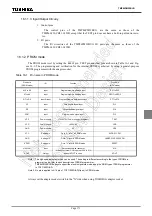
16.1.2 PROM mode
The PROM mode is set by setting the
RESET
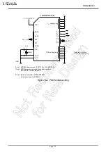
pin, TEST pin and other pins as shown in Table 16-1 and Fig-
ure 16-2. The programming and verification for the internal PROM is acheived by using a general-purpose
PROM programmer with the adaptor socket.
Note 1: The high-speed program mode can be used. The setting is different according to the type of PROM pro-
grammer to use, refer to each description of PROM programmer.
TMP86PM29BUG does not support the electric signature mode, apply the ROM type of PROM programmer
to TC571000D/AD.
Note 2: No pin is applied to A16 pin of TC571000D/AD(Open) in PROM mode.
Always set the adapter socket switch to the "N" side when using TOSHIBA’s adaptor socket.
Table 16-1 Pin name in PROM mode
Pin name
(PROM mode)
I/O
Function
Pin name
(MCU mode)
A15 to A8
Input
Program memory address input
P57 to P50
A7 to A0
Input
Program memory address input
SEG7 to SEG0
D7 to D0
Input/Output
Program memory data input/output
P77 to P70
CE
Input
Chip enable signal input
P13
OE
Input
Output enable signal input
P14
PGM
Input
Program mode signal input
P15
VPP
Power supply
+12.75V/5V (Power supply of program)
TEST
VCC
Power supply
+6.25V/5V
VDD
GND
Power supply
0V
VSS
VCC
Setting pin
Fix to "H" level in PROM mode
AVDD,P11,P21
GND
Setting pin
Fix to "L" level in PROM mode
VAREF,P10,P20,P22,P61
RESET
Setting pin
Fix to "L" level in PROM mode
RESET
XIN (CLK)
Input
Set oscillation with resonator
In case of external CLK input, set CLK to XIN
and set XOUT to open.
XIN
XOUT
Output
XOUT
Содержание TLCS-870/C Series
Страница 1: ...8 Bit Microcontroller TLCS 870 C Series TMP86PM29BUG ...
Страница 6: ...TMP86PM29BUG ...
Страница 7: ...Revision History Date Revision 2007 10 11 1 First Release 2008 8 29 2 Contents Revised ...
Страница 9: ......
Страница 15: ...vi ...
Страница 19: ...Page 4 1 3 Block Diagram TMP86PM29BUG 1 3 Block Diagram Figure 1 2 Block Diagram ...
Страница 23: ...Page 8 1 4 Pin Names and Functions TMP86PM29BUG ...
Страница 48: ...Page 33 TMP86PM29BUG ...
Страница 49: ...Page 34 2 Operational Description 2 3 Reset Circuit TMP86PM29BUG ...
Страница 61: ...Page 46 3 Interrupt Control Circuit 3 8 External Interrupts TMP86PM29BUG ...
Страница 81: ...Page 66 6 Watchdog Timer WDT 6 3 Address Trap TMP86PM29BUG ...
Страница 135: ...Page 120 10 8 Bit TimerCounter TC5 TC6 10 1 Configuration TMP86PM29BUG ...
Страница 145: ...Page 130 11 Asynchronous Serial interface UART 11 9 Status Flag TMP86PM29BUG ...
Страница 165: ...Page 150 13 10 bit AD Converter ADC 13 6 Precautions about AD Converter TMP86PM29BUG ...
Страница 183: ...Page 168 15 LCD Driver 15 4 Control Method of LCD Driver TMP86PM29BUG ...
Страница 201: ...Page 186 18 Electrical Characteristics 18 9 Handling Precaution TMP86PM29BUG ...
Страница 203: ...Page 188 19 Package Dimensions TMP86PM29BUG ...
Страница 205: ......

