


______________________________________________________________________________
2007 Toshiba America Consumer Products, LLC.
Page 3 of 12
SMART2006001_Version2.2
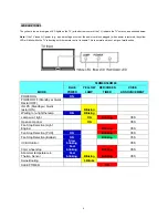
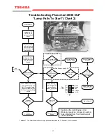
Does the Color
Wheel Start?
Check for 5vdc on
pin 3 of plug CN3
on the Ballast
Board (5 pin plug)
Fig. 1
Is the 5vdc
present?
Go to Chart 3
No
Yes
Check Ribbon Cable from
the Color Wheel to the
DMD Formatter Board.
Connector labeled [CW
OUT] on Formatter Metal
Shield
See
Footnote 1.
Problem
Resolved?
Yes
From Chart 1
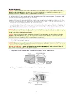
Troubleshooting Flowchart 2006 DLP
“Lamp Fails To Start” (Chart 2)
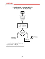
Is Thermal
Sensor across
P805 Open?
Reset Thermal
Sensor
Change Ballast
Power Supply
Yes
No
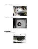
Replace Optical
Engine
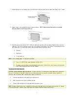
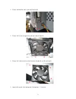
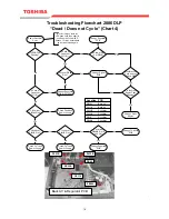
Unplug the TV
from AC and
remove the back
cover
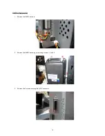
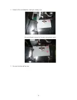
Remove 2 screws
holding the optic
engine in place
and slide back to
gain access.
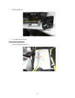
Re-Apply AC and
Power the set on
using the power
button.
12v present on
J11 Pins 1,2?
120vac across
P807B?
Approx 300v
present across
P811A?
No
Yes
Check Chassis
Power Supply
Yes
No
Yes
Yes
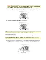
Plug
CN3
Pin 1
Pin 2
Pin 3
Pin 4
Pin 5
Fig. 1
Black
Brown
Red
Orange
Yellow
No
No
Repair
Connections
DMD Formatter PCB
Ballast Power Supply PCB
Footnote 1. The Color Wheel will emit a high pitched whine when the TV Receiver is first turned on.
V1.0
No
Replacing the Light Engine under
Warranty requires a concession number
to be obtained from Technical Support.
1-800-345-9785
17
Содержание TheaterWide 50HM66
Страница 26: ...25 ...
Страница 27: ...26 ...
Страница 28: ...27 ...
Страница 34: ...TOSHIBA CORPORATION 1 1 SHIBAURA 1 CHOME MINATO KU TOKYO 105 8001 JAPAN ...


