background image

5-1

5. SET UP PROCEDURE

EO1-33019

5. SET UP PROCEDURE

5.1 REQUIREMENTS FOR OPERATION

This machine has the following requirements:

The host computer must have a serial port or centronics parallel port.

To communicate with host, either an RS-232C cable or Centronics cable is required.
(1) RS-232C cable .......... 9 pins
(2) Centronics cable ....... 36 pins

To print a label format, create the complete program using the interface/communication manual or use
a bespoke labelling package or Windows Driver.

Interface Cables

To prevent radiation and reception of electrical noise, the interface cables must meet the following
requirements:

Fully shielded and fitted with metal or metalised connector housings.

Kept as short as possible.

Should not be bundled tightly with power cords.

Should not be tied to power line conduits.

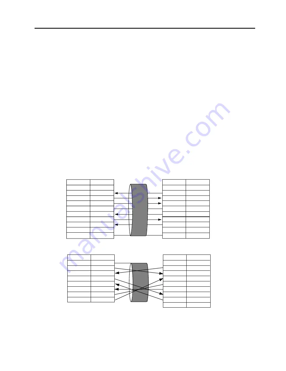
RS-232C Cable description

The serial data cable used to connect the printer to the host computer should be one of the following two
types:
NOTE: Use an RS-232C cable with imperial (inch) connector securing screws.

5.1 REQUIREMENTS FOR OPERATION

DB-9S

Connector to PC

DB-9P

Connector to Printer

DB-25S

Connector to PC

DB-9P

Connector to Printer

PIN No.

1
2
3
4
5
6
7
8
9

Housing

Signal

N.C.

RXD

TXD
DTR

GND

DSR

RTS
CTS
N.C.

Shield

PIN No.

1
2
3
4
5
6
7
8
9

Housing

Signal

N.C.
TXD

RXD
DSR

GND

DTR
CTS
RTS
N.C.

Shield

PIN No.

1
2
3
4
5
6
7

20

Signal
Shield

TXD

RXD

RTS
CTS

DSR

GND

DTR

PIN No.

1
2
3
4
5
6
7
8
9

Signal

N.C.
TXD

RXD
DSR

GND

DTR
CTS
RTS
N.C.

5.2 SETTING UP THE PRINTER

Place the printer on a flat, stable surface.

Use a grounded electrical outlet do not use adapter plug.

Be sure there is adequate room around the printer for easy operation and maintenance.

Keep your work environment static free.

Fig. 5-1

Содержание TEC B-450-HS-QQ Series

Страница 1: ...TEC Label Printer B 450 HS QQ SERIES Owner s Manual ...

Страница 2: ...d and used in accordance with the instruction manual may cause harmful interference to radio communications Operations of this equipment in a residential area is likely to cause harmful interference in which case the user will be required to correct the interference at his own expense for USA only ThisClassAdigitalapparatusmeetsallrequirementsoftheCanadianInterference CausingEquipment Regulations ...

Страница 3: ...s indication Prohibited Do not plug in or unplug the power cord plug with wet hands as this may cause electric shock Do not place metal objects or water filled containers such as flower vases flower pots or mugs etc on top of the machines If metal objects or spilled liquid enter the machines this may cause fire or electric shock If the machines share the same outlet with any other electrical appli...

Страница 4: ... ribbons DO NOT STORE the paper or ribbons where they might be exposed to direct sunlight high tem peratures high humidity dust or gas Ensure the printer is operated on a level surface Any data stored in the memory of the printer could be lost during a printer fault Try to avoid using this equipment on the same power supply as high voltage equipment or equip ment likely to cause mains interference...

Страница 5: ...HE SUPPLY HOLDER UNIT 6 1 6 2 INSTALLING THE SUPPLY COVER 6 1 6 3 CONNECTING THE POWER CORD AND CABLES 6 2 7 LOADING THE RIBBON 7 1 8 LOADING THE PAPER 8 1 9 THRESHOLD SETTING 9 1 10 CARE HANDLING OF THE PAPER AND RIBBON 10 1 11 GENERAL MAINTENANCE 11 1 11 1 CLEANING 11 1 11 2 COVERS 11 2 11 3 REMOVING JAMMED PAPER 11 3 12 TROUBLESHOOTING 12 1 APPENDIX 13 1 INDEX Page CAUTION 1 This manual may not...

Страница 6: ...ude a strip mechanism and cutter mechanism This manual contains general set up and maintenance information and should be read carefully to help gain maximum performance and life from your printer For most queries please refer to this manual and keep it safe for future reference 1 1 APPLICABLE MODEL B 452 HS12 QQ B 452 HS12 QQ US Model name description B 4 5 2 H S 1 2 Q Q Destination Code QQ US Nor...

Страница 7: ... 6 mm 4 08 inches Dispensing modes Batch Continuous Strip Option and Cut modes Option Bothcutandstripmodesareavailableonlywhentheirrespectivemodules are fitted Available bar code types JAN8 JAN13 EAN8 EAN8 2 digits EAN8 5 digits EAN13 EAN13 2 digits EAN13 5 digits UPC E UPC E 2 digits UPC E 5 digits UPC A UPC A 2 digits UPC A 5 digits UPC B MSI ITF NW 7 CODE39 CODE93 CODE128 EAN128 Industrial 2 to...

Страница 8: ...d up slow down area Outer roll diameter Thickness Backing paper label Thickness of backing paper Labeldispensingmode Item Batch mode Strip mode Cut mode 25 4 999 0 23 4 997 0 25 4 110 0 20 0 107 0 2 0 20 0 2 0 10 0 10 0 103 6 21 4 200 0 1 0 MAX ø152 4 Paper Core ø38 40 42 or 76 2 0 13 0 17 0 056 2 0 20 0 3 0 200 0 6 0 20 0 29 0 200 0 0 1 0 17 0 1 0 17 7 0 999 0 5 0 997 0 37 0 999 0 31 0 993 0 NOTE...

Страница 9: ...n a communication error occurs when the paper ribbon ends or the printer is not operating cor rectly FEED Key Feeds paper PAUSE Key Pauses printing Resets the printer when paused or when an error occurs Fig 3 2 Operation Panel Power Switch O OFF I ON Paper Outlet Fig 3 1 DIP Switch Top Cover Paper Guide Lock Lever Supply Holder AC Power Inlet Serial Interface Con nector RS 232C Keyboard Connector ...

Страница 10: ...tting mode Sensor adjustment mode RAM clear mode Parameter Normal operation mode Program down load operation Remarks Transmission speed Baud rate Parity Stacker Auto media feed Selectable only when DIP SW 8 is ON Operating mode DIP SW NOTES 1 DIP Switch settings are read at power on time 2 To enter the program download mode first set DIP SW 8 to ON The printer will then enter down the FEED or FEED...

Страница 11: ...rds Should not be tied to power line conduits RS 232C Cable description The serial data cable used to connect the printer to the host computer should be one of the following two types NOTE Use an RS 232C cable with imperial inch connector securing screws 5 1 REQUIREMENTS FOR OPERATION DB 9S Connector to PC DB 9P Connector to Printer DB 25S Connector to PC DB 9P Connector to Printer PIN No 1 2 3 4 ...

Страница 12: ...nit 6 2 INSTALLING THE SUPPLY COVER Fit both hooks of the supply cover onto the shafts of the supply holder and then gently close the supply cover Refer to Fig 6 2 NOTE After this section the supply cover will be removed in photos and figures Please understand that it provides clearer descriptions Fig 6 1 WARNING Turn the power OFF before installing the supply holder unit Supply Holder Unit Fig 6 ...

Страница 13: ...ial Interface RS 232C WARNING Turn the POWER SWITCH to OFF before connecting the power cord or cables Parallel Interface Cable Centronics 6 3 CONNECTING THE POWER CORD AND CABLES 6 3 CONNECTING THE POWER CORD AND CABLES Keyboard Interface Expansion I O Interface ...

Страница 14: ... side 4 Pull the knob and set the ribbon core to the spring guide wheel Guide Wheel Protrusion Notch Knob Spring Guide Wheel Ribbon Core Take up side The printer is capable of printing in thermal transfer mode only 1 Turn the power off and open the top cover 2 Move the head release lever toward the front of the printer and raise the print head block WARNING Be careful when handling the print head ...

Страница 15: ... side by fitting the protrusion into the notch 6 Turn the guide wheel in the direction indicated by the arrow to remove any slack on the ribbon NOTE Make sure that the ribbon has no wrinkles and the protrusions are fitted into the notches of the ribbon cores Fig 7 3 Fig 7 4 Guide Wheel ...

Страница 16: ...older This supply holder accepts four sizes of label core 38 mm 40 mm 42 mm and 76 2 mm When using a paper roll of 38 mm 40 mm or 42 mm remove the spacers from the supply holders using the following procedure 1 Remove the supply cover 2 Push both hooks of the spacer to remove it from the supply holder Keep the removed spacers safe WARNING Be careful when handling the print head as it becomes very ...

Страница 17: ...sure that the supply holders rotate slightly Fig 8 4 Paper wound inside 6 Lift up the paper guide lock lever to release the paper guides 7 Draw the label towards the paper guides 8 Release the lock lever in the direction indicated by the arrow and gently lift the sensor cover NOTE Lift the sensor cover gently so that it does not touch the ribbon 9 Adjust the position of the paper guides to the lab...

Страница 18: ...etting the feed gap sensor position and adjust the sensor position 11 Draw the label onto the platen Close the sensor cover and return the lock lever to lock the sensor cover tight 12 Close the print head block by pressing both sides of the print head block s top until it clicks Fig 8 7 Head Block Fig 8 8 Supply Holder Paper Guide Paper Platen A B A B NOTE Pass the paper straight from the supply h...

Страница 19: ...on the label will cause the glue to stick to the cutter which may affect the cutter quality and shorten it s life Cutter Module Paper Outlet Paper Batch type Fig 8 9 Top Cover Fig 8 10 Strip type 1 Strip the labels from the backing paper for about 200 mm from the top edge of the label roll 2 First push the strip lever toward the printer to release the hook and then pull the strip lever 3 Pass the ...

Страница 20: ...ly so that it does not touch the ribbon 3 Set sensor knob B to the same position number as the sensor knob A NOTE The sensor knobs A and B are set to the position 3 where the black mark is centred in the label width as a default Do not change the position of sensor knobs A and B except when changing the sensor detecting position Be sure to set sensor knobs A and B to the same position Failure to d...

Страница 21: ...over gently so that it does not touch the ribbon 3 Set the sensor knob B to the same position of the sensor knob A NOTE Sensor knobs A and B are set to position 3 where the black mark is centred on the label width asadefault DonotchangethepositionofsensorknobsAandBexceptwhenchangingthesensor detecting position Be sure to set the sensor knobs A and B to the same position Failure to do this may caus...

Страница 22: ...SE key The paper will feed through the printer until the PAUSE key is released Release the PAUSE key after more than 1 5 labels have been fed Threshold setting is completed by this operation 6 Turn the power OFF NOTES 1 Tosetthethresholdproperly besuretofeedmorethan1 5labels Insufficientpaperfeeding may result in an incorrect threshold setting In this case repeat the procedure 2 While the print he...

Страница 23: ...rmal paper used for direct thermal printing must not have specifications that exceed Na 800 ppm K 250 ppm and CL 500 ppm Some ink used on pre printed labels may contain ingredients which shorten the print head s product life Do not use labels pre printed with ink which contain hard substances such as carbonic calcium CaCO3 and kaolin Al2 O3 2SiO2 2H2 O For further information please contact your l...

Страница 24: ...thorized TOSHIBA TEC service representative Print Head Thermal Element WARNING 1 Be sure to disconnect the power cord prior to performing any maintenance 2 DO NOT POUR WATER directly onto the printer Fig 11 1 Print Head Cleaner 24089500013 CAUTION 1 Do not use any sharp objects to clean the print head and platen Doing so may damage them causing poor print quality or missing dots 2 Never use organi...

Страница 25: ... Holder Roller Recessedportionofthebase Supply Holder Base Platen Black mark Feed gap sensor 11 2 COVERS The covers should be cleaned by wiping with a dry cloth or a cloth slightly dampened with a mild detergent solution NOTE Clean printer cover with an electrostatic free cleaner for automated office equipment WARNING 1 DO NOT POUR WATER directly onto the printer 2 DO NOT APPLY cleaner or detergen...

Страница 26: ...he print head and platen then remove any further dust or foreign substances 8 Paper jams in the cutter unit can be caused by wear or residual glue from label stock on the cutter Do not use unspecified paper in the cutter If frequent jams occur in the cutter contact your Authorized Service representative Fig 11 4 Print Head Block Top Cover Head Release Lever Cleaning the Cutter Unit 1 Press the cut...

Страница 27: ...Strip Unit 1 First push the strip lever toward the printer to release the hook and then pull the strip lever 2 Remove the jammed paper if any 3 Clean the strip guide rollers A and B with a cloth moistened with alcohol WARNING 1 Be sure to disconnect the power cord before cleaning the strip unit 2 Do not touch the moving parts To reduce the risk that fingers jewellery clothing etc be drawn into the...

Страница 28: ...ized Service represen tative Problem 1 The paper is not fitted correctly 2 The paper path is jammed and does not feed smoothly 3 The installed paper type does not match the selected sensor 4 The installed paper size is different from the programmed size 5 The feed gap sensor cannot see the difference between the print area and the gap Feeding or printing has been attempted while the print head is ...

Страница 29: ...r has been switched off and on all the print data in the printer is cleared Solution 1 Check that the paper and ribbon are loaded correctly 2 Check that print head is set correctly 3 Check the cabling between the printer and the host Dirty print head Clean the print head Call your Authorized Service representative if necessary 1 Dirty print head Clean the print head 2 Bad or faulty ribbon Replace ...

Страница 30: ...13 1 EO1 33019 APPENDIX APPENDIX APPENDIX ASCII Code Chart Font Sample Barcode Sample ...

Страница 31: ...yboard module 2 2 Strip mechanism 1 1 Strip module 2 2 P Paper 2 2 10 1 Paper jam 12 1 Power consumption 2 1 Power cord 1 1 6 2 Power switch 3 1 Print head 1 1 2 1 11 1 Print head cleaner 11 1 Print length 2 2 Print speed 2 1 Print width 2 2 Printing method 2 1 Program down load operation 4 1 R Relative humidity 2 1 Resolution 1 1 Ribbon 2 2 7 1 10 1 S Sensor knob A 8 5 8 6 Sensor knob B 8 5 8 6 S...

Страница 32: ......

Страница 33: ......

Страница 34: ...PRINTED IN JAPAN EO1 33019 E ...

Отзывы: