1
6
0
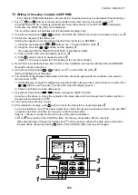
2. Every pushing [Unit, Louver
UNIT LOUVER
] button, the indoor unit address in the group are displayed successively.
2
Specify the indoor unit No. to be replaced.
3. Using the set temperature
/
buttons, the CODE No. (DN) can be moved up and down one by one.
3
4. First change the CODE No. (DN) from
to
. (Setting of filter sign lighting time)
Make a note of the set data displayed in this time.
5. Next change the CODE No. (DN) using the set temperature
/
buttons.
Also make a note of the set data.
6. Repeat item 5. and made a note of the important set data as shown in the below table.
∗
to
))
are provided in the CODE No. (DN). On the way of operation, DN No. may skip.
7. After finishing making a note, push
TEST
button to return to the usual stop status.
4
(Approx. 1 minute is required to be able to use the remote controller.)
Minimum requirements for CODE No.
Capacity of the indoor unit is necessary to set
the revolutions of the fan.
H
2 Replacement of service P.C. board
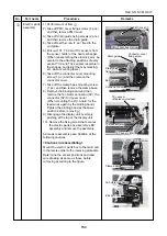
1. Replace the P.C. board with a service P.C. board.
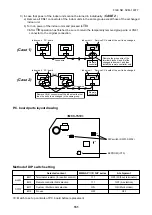
In this time, setting of jumper line (cut) or setting of DIP switch on the former P.C. board should be reflected
on the service P.C. board. Refer to the following table about DIP switch setting and drawing of P.C. board
parts layout.
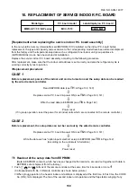
2. It is necessary to set Indoor unit to be exchanged : Remote controller = 1 : 1
Based upon the system configuration, turn on power of the indoor unit with one of the following items.
1) Single (Individual) operation
Turn on power of the indoor units and proceed to
H
3
.
2) Group operation
A) In case that power of the exchanged indoor unit only can be turned on.
Turn on power of the exchanged indoor unit only and proceed to
H
3
.
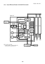
B) In case that power of the indoor units cannot be turned on individually. (
CASE 1
)
a) Remove temporarily the group wire connected to the terminal blocks A and B of the exchanged
indoor unit.
b) After connecting the remote controller wire only to the removed terminal block, turn on power of
the indoor units and proceed to
H
3
.
* When the above methods cannot be used, follow at the
CASE 2
below.
DN
11
12
13
14
Contents
Indoor unit capacity
Refrigerant line address
Indoor unit address
Group address
4
3
1
2
TEMP.
ON / OFF
SET
TIME
TEST
FILTER
RESET
CL
SAVE
SWING/FIX
VENT
UNIT LOUVER
CODE No.
UNIT No.
R.C. No.
TIMER SET
MODE
FAN
SET DATA
SETTING
FILE NO. SVM-1
40
77

