Universal Slot PCBs
3-26
Strata CT I&M Manual October 2000
PACU - AC15 Tie Line Unit
System:
Strata CT
Circuits per PCB:
four AC15 tie lines
Interfaces with:
AC15 ‘type A’ circuits
Older Version(s):
PACU1
Each PACU Interface Unit decreases the maximum number of system exchange lines by four.
Each PACU Interface Unit will support four AC15 ‘type A’ tie lines. If the system is
connected to another Strata system (or any system in compliance with BTNR181, section 4)
the recall feature inherent in AC15 ‘type C’ signalling which allows anti-tromboning will be
available.
Note
For the system to recognise the DTMF tones generated by incoming TIE lines a
DTMF receiver unit (BRCS) must be installed on the Strata CT Processor PCB.
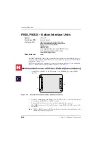
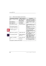
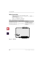
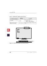
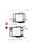
PACU controls, indicators and interface connectors are shown in
and described
PACU Installation
1.
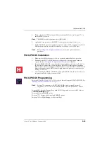
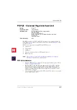
Insert the PACU (component side facing right) into the appropriate Expansion cabinet
slot and apply firm, even pressure to ensure proper mating of the connectors.
Important!
Each PACU decreases the maximum system exchange lines by four.
2.
After installing, gently pull the PACU outward. If the connectors are properly mated, a
slight resistance is felt.
H
C
Содержание Strata CT
Страница 36: ...Strata CT Configuration 1 22 Strata CT I M Manual October 2000 H C ...
Страница 94: ...Strata CT Installation 2 58 Strata CT I M Manual October 2000 H C ...
Страница 242: ...Peripheral Installation 6 54 Strata CT I M Manual October 2000 H C ...
Страница 258: ...ACD Installation 7 16 Strata CT I M Manual October 2000 H C ...
Страница 274: ...Fault Finding 8 16 Strata CT I M Manual October 2000 H C ...
Страница 326: ...Computer Telephony Integration Handling Incoming Calls 9 52 Strata CT I M Manual October 2000 H C ...
Страница 364: ...ISDN Interfaces 10 38 Strata CT I M Manual October 2000 H C ...
Страница 370: ...Notes to Users A 6 Strata CT I M Manual October 2000 H C ...

