ISDN Interfaces
Timing and Synchronization
16-40
Strata DK I&M 6/00
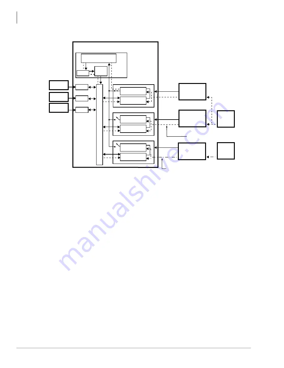
Figure 16-31 Primary and Secondary References
shows the Primary reference PCB. The clock signal from Line 1 passes through
the PCB Software Switch (SS
1
) and the synchronization circuit of the RCTU PCB. The RCTU
clock passes the clock source through the time switch and synchronizes the DK424 or DK424i
digital transmission voice or data path.
The Secondary reference is activated if the Primary reference fails. The DK424 or DK424i
automatically
switches over
to the Secondary reference PCB by opening its synchronization
circuit (SS
1
) and closing the synchronization circuit (SS
2
). When this occurs, the digital voice
or data path of the DK424 or DK424i is synchronized to the Line 2 clock source.
If the path is not synchronized to the Stratum – 1 clock source, calls connected through that
path experience “slipping” or “jitter” in the digital voice or data path (channels). Figure 14-7
shows an unsynchronized signal from Line 3. The unsynchronized signal produces a clicking
or popping sound that is heard by the people connected through this path or causes data errors
on data transmissions.
4773
PDKU
Primary Reference PCB*
Secondary Reference PCB*
Other RDTU, RPTU, or RBSU
DK424
Digital T
ransmission V
oice
P
ath
Synchronization
Circuit
Synchronization
Circuit
Synchronization
Circuit
Digital Voice
Path
Digital Voice
Path
Digital Voice
Path
DK40i, DK424 or DK424i
Digital
Telephone
Electronic
Telephone
Standard
Telephone
SS1
SS2
SS3
Line 1
Line 2
Line 3
Public Switched
Telephone
Network (PSTN)
PRI, BRI, or T1
AT&T or
other provider
PRI, BRI, or T1
Other
PRI, BRI, or T1
provider
Stratum-1
Clock
Source
Processor PCB
Clock not synchronized properly
with Stratum-1 Clock Source
Time
Switch
Clock
Synchronization
Circuit
Prg *42-1-1
Prg *41-1[blank]
Prg *42-2-2
Prg *42-1[blank]
Clock synchronized properly
with Stratum-1 Clock Source
Other
Clock
Source
RSTU
PEKU
* Primary/Secondary reference
PCBs are assigned in
Programs
*
42-1/
*
42-2 and
can be an RDTU, RPTU,
RBSU, RBUU, TBUS or TBUU.
Содержание Strata AirLink DK40i
Страница 22: ...Introduction Related Documents Media xx Strata DK I M 6 00 ...
Страница 48: ...DK14 Installation DK14 Wiring Diagrams 1 26 Strata DK I M 6 00 ...
Страница 220: ...DK424 Installation Remote Cabinet Installation Instructions 5 68 Strata DK I M 6 00 ...
Страница 262: ...DK424i Configuration Primary Reserve Power Cabinet Hardware 6 42 Strata DK I M 6 00 ...
Страница 450: ...Universal Slot PCB Wiring Option Interface PCB Wiring Diagrams 10 42 Strata DK I M 6 00 ...
Страница 592: ...Peripheral Installation Enhanced 911 Service E911 12 84 Strata DK I M 6 00 ...
Страница 616: ...ACD Installation Spectrum Electronic Wall Boards 13 24 Strata DK I M 6 00 ...
Страница 634: ...Fault Finding Fault Isolation Flowcharts 14 18 Strata DK I M 6 00 ...
Страница 704: ...ISDN Interfaces ISDN Disconnect Cause Code 16 54 Strata DK I M 6 00 ...


