Station Apparatus
Telephone Upgrades
Strata DK I&M 6/00
11-13
Station Apparatus
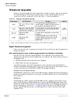
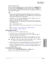
Data Communications Mode
In the data communications mode, data calls can be from a telephone with the
'DWD&DOO
button
and disconnected with the
'DWD5HOHDVH
button. Digital telephones can have a
0RGHP
button
for reserving a modem or monitoring modem availability and status. These feature buttons are
assigned to telephones with Program 39. Data and voice calls can be dialed from a terminal or PC
using standard “AT” commands.
Notes
●
1000-series digital telephones with an RPCI-DI or PDIU-DI2 cannot be wall-mounted or
equipped with an Add-On-Module (ADM) or DVSU for Speaker OCA. A 2000-series digital
telephone with a PDIU-DI2 or RPCI-DI can support an HHEU at the same time, but cannot
support a DVSU or ADM and can be wall-mounted.
●
Only PDKU1 circuits 1~7 can support RPCI-DI or PDIU-DI2s; all PDKU2 and Base Unit
digital circuits can support PDIU-DI2 and RPCI-DIs.
●
RPCI-DIs and PDIU-DI2s that support data communications mode, must be connected to
digital telephone circuits that support 2B channels. The digital circuits that support RPCI-DI
data communication are:
DK14 – all digital telephone circuits.
DK40i – all digital telephone circuits except those installed in slot 17 and 18 of the expansion
unit.
DK424 – see
of the
Chapter 4 – DK424 Configuration
DK424i – see
Chapter 6 – DK424i Configuration
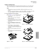
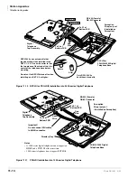
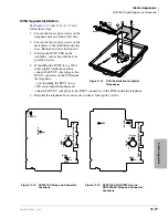
RPCI-DI/PDIU-DI2 Installation
See
,
and
and follow these steps:
1. Loosen the four screws on the digital telephone base and remove the base.
2. Insert the two integrated unit wire plugs into the connectors on the PCB in the telephone
(observing the red wire for correct positioning).
3. Attach the integrated unit to the bottom of the phone. Install the PDIU-DI for 1000-series;
install PDIU-DI2 or RPCI-DI for 2000-series phones. Secure with the four captive screws.
Note
RPCI-DI V2s require some modification when installed in DKT versions 1~3; RPCI-DI
V2s in DKT version 4 or higher do not require any modification.
4. Remove the directory tray from the original telephone base and install it on the integrated unit
phone base. Squeeze the tray on its sides so it bows slightly to remove and re-install.
5. See Chapter 5 – DK424 Installation,
for loop limits. Install a two-pair
house cable (or external power) and a two-pair modular cord (supplied with PDIU-DI), if
required for distance.
RPCI, PDIU-DI1/PDIU-DI2 Programming
Program 39: Assigns the
'DWD&DOO
,
'DWD5HOHDVH
, and
0RGHP
buttons.
Programs 20 and 22: RPCI and data interface unit assignments.
Содержание Strata AirLink DK40i
Страница 22: ...Introduction Related Documents Media xx Strata DK I M 6 00 ...
Страница 48: ...DK14 Installation DK14 Wiring Diagrams 1 26 Strata DK I M 6 00 ...
Страница 220: ...DK424 Installation Remote Cabinet Installation Instructions 5 68 Strata DK I M 6 00 ...
Страница 262: ...DK424i Configuration Primary Reserve Power Cabinet Hardware 6 42 Strata DK I M 6 00 ...
Страница 450: ...Universal Slot PCB Wiring Option Interface PCB Wiring Diagrams 10 42 Strata DK I M 6 00 ...
Страница 592: ...Peripheral Installation Enhanced 911 Service E911 12 84 Strata DK I M 6 00 ...
Страница 616: ...ACD Installation Spectrum Electronic Wall Boards 13 24 Strata DK I M 6 00 ...
Страница 634: ...Fault Finding Fault Isolation Flowcharts 14 18 Strata DK I M 6 00 ...
Страница 704: ...ISDN Interfaces ISDN Disconnect Cause Code 16 54 Strata DK I M 6 00 ...


