Universal Slot PCBs
RDTU – T1 Interface Unit
9-62
Strata DK I&M 6/00
RMCU Installation
1. Insert the RMCU (component side facing right) into the appropriate slot, and apply firm, even
pressure to ensure proper seating of the connectors.
2. Gently pull the unit outward. If the connectors are properly seated, a light resistance is felt.
3. Wire the RCMS jacks, J4 and J5, to the network CAMA trunks per
4. Test the CAMA trunk and set the 3-dB PAD switches, SW101 and SW 201, for the appropriate
volume level.
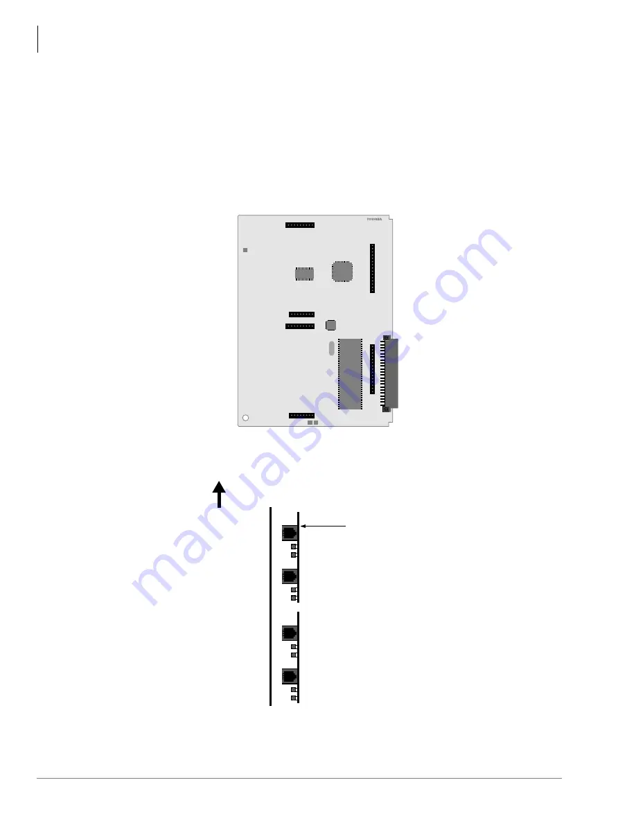
Figure 9-33 RMCU Interface Card
Figure 9-34 Location of the RCMS LEDs
R M C U 1 A
- C M V. 1
RMCU1A
3005
RMCU1A
P6
P5
P7
P3
P2
P4
RMCUV.1
RMC21B
TC35354F
RMCU1A
2796
RCMS1A (2/2)
LEDs (indicate Trunk Condition)
Network Busy (NB) LED
Customer Busy (CB) LED
RCMS1A (1/2)
RJ11 2-Pin Modular Connector
CAMA #4
CAMA #3
CAMA #2
CAMA #1
TOP
NB LED
CB LED
NB LED
CB LED
NB LED
CB LED
Содержание Strata AirLink DK40i
Страница 22: ...Introduction Related Documents Media xx Strata DK I M 6 00 ...
Страница 48: ...DK14 Installation DK14 Wiring Diagrams 1 26 Strata DK I M 6 00 ...
Страница 220: ...DK424 Installation Remote Cabinet Installation Instructions 5 68 Strata DK I M 6 00 ...
Страница 262: ...DK424i Configuration Primary Reserve Power Cabinet Hardware 6 42 Strata DK I M 6 00 ...
Страница 450: ...Universal Slot PCB Wiring Option Interface PCB Wiring Diagrams 10 42 Strata DK I M 6 00 ...
Страница 592: ...Peripheral Installation Enhanced 911 Service E911 12 84 Strata DK I M 6 00 ...
Страница 616: ...ACD Installation Spectrum Electronic Wall Boards 13 24 Strata DK I M 6 00 ...
Страница 634: ...Fault Finding Fault Isolation Flowcharts 14 18 Strata DK I M 6 00 ...
Страница 704: ...ISDN Interfaces ISDN Disconnect Cause Code 16 54 Strata DK I M 6 00 ...


