DK424 Installation
Reserve Power Installation
Strata DK I&M 6/00
5-33
DK424 Installa
tion
Reserve Power for One or Two Cabinets (Wall Mount)
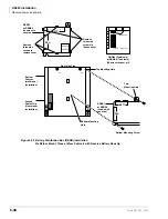
1. Connect the black jumper wire (supplied with the PBTC-3M cable) from the positive terminal
of one 12VDC battery to the negative terminal of the second 12VDC battery (
).
2. Ensure that a serviceable 10-amp fuse is installed in the in-line fuse holder of the PBTC-3M
cable.
3. Connect the PBTC-3M battery cable white lead to the open positive terminal of the 12VDC
battery. Connect the black lead to the open negative terminal of the second 12VDC battery.
Important!
The cabinet(s) must be connected to the (live) AC power source, and the power
supply On/Off switch set to On prior to the final step of connecting the reserve
power batteries to the power supply via the BATT+/- receptacle. If the batteries are
connected after AC power is lost, reserve power will not function.
4. Connect the PBTC-3M battery cable two-prong male plug to the Base Cabinet power supply
BATT +/- receptacle.
5. Repeat Steps 3 and 4 to connect a PBTC-3M to the Expansion Cabinet.
6. To test reserve power operation, disconnect system AC power plugs with power supply On/
Off switches in the On position. The system should continue to operate without interruption.
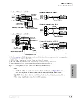
Note
If connecting four batteries, follow the wiring diagram in
Reserve Power for Three or More Cabinets (Wall Mount)
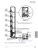
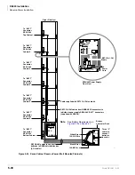
1. Install the Battery Distribution Box (RBDB1A or RBDB2) to the bottom cabinet.
2. Connect two Cable “C” jumper wires from the positive terminal of one 12VDC battery to the
negative terminal of the second 12VDC battery (Cable “C” is supplied with the RBTC1A-2M
cable).
3. Ensure that a serviceable 12-amp fuse is installed in the in-line fuse holder of the RBTC1A-
2M battery cable.
4. Connect the white lead of the RBTC1A-1.5M or RBTC2A-1.7M battery cable to the open
positive terminal of the 12VDC battery. Connect the black lead to the open negative terminal
of the second 12VDC battery.
5. Connect a second RBTC1A-1.5M or RBTC2A-1.7M in parallel to the first RBTC1A-2M
cable per Steps 2, 3 and 4 instructions.
6. Plug the two RBTC1A-1.5M or RBTC2A-1.7M battery cables into the Battery Distribution
Box.
Important!
The cabinets must be connected to the (live) AC power source, and the power supply
On/Off switches set to On prior to the final step of connecting the reserve power
batteries to the power supplies via the BATT +/- receptacle. If the batteries are
connected after AC power is lost, reserve power will not function.
7. Connect the RBTC1A-1.5M or RBTC2A-1.7M cables from the Battery Distribution Box to
the BATT +/- receptacle of individual power supplies (6-RBTC1A-1.5M cables are supplied
with an RBDB distribution box). RBTC2A-1.7M is required for the seventh cabinet. It must be
ordered with part number RCTC1A-1.7A.
8. To test reserve power operation, disconnect the system AC power plugs with the power supply
On/Off switches in the On position. The system should continue to operate without
interruption.
Note
If connecting four batteries, follow the wiring diagrams in
Содержание Strata AirLink DK40i
Страница 22: ...Introduction Related Documents Media xx Strata DK I M 6 00 ...
Страница 48: ...DK14 Installation DK14 Wiring Diagrams 1 26 Strata DK I M 6 00 ...
Страница 220: ...DK424 Installation Remote Cabinet Installation Instructions 5 68 Strata DK I M 6 00 ...
Страница 262: ...DK424i Configuration Primary Reserve Power Cabinet Hardware 6 42 Strata DK I M 6 00 ...
Страница 450: ...Universal Slot PCB Wiring Option Interface PCB Wiring Diagrams 10 42 Strata DK I M 6 00 ...
Страница 592: ...Peripheral Installation Enhanced 911 Service E911 12 84 Strata DK I M 6 00 ...
Страница 616: ...ACD Installation Spectrum Electronic Wall Boards 13 24 Strata DK I M 6 00 ...
Страница 634: ...Fault Finding Fault Isolation Flowcharts 14 18 Strata DK I M 6 00 ...
Страница 704: ...ISDN Interfaces ISDN Disconnect Cause Code 16 54 Strata DK I M 6 00 ...


