background image

T

HE

 G

RAND

 T

OUR

  2-1

Chapter 2

The Grand Tour

This chapter identifies the various components of your computer. Become familiar
with each component before you operate the computer.

Front with the display closed

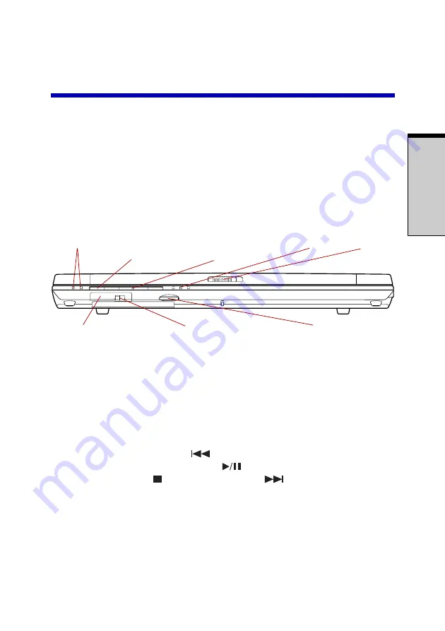
Figure 2-1 shows the computer’s front with its display panel in the closed position.

I

NDICATORS

 (1) M

ODE


CONTROL

A

UDIO

/V

IDEO

I

NDICATORS

 (2) D

ISPLAY


LATCH

BUTTON

CONTROL


BUTTONS

I

NFRARED


PORT

W

IRELESS


COMMUNICATION


SWITCH

V

OLUME


CONTROL

Figure 2-1  Front of the computer with display closed

Indicators (1)

Two LEDs let you monitor the play of audio CD and MP3
status. Details are in the 

Indicators

 section.

Mode Control

Press this button to switch the mode between CD/DVD

button

and Digital Audio. Refer to Chapter 4, 

Operating Basics

.

Audio/Video

Previous 


button: Plays the previous track/chapter/

 control buttons

data. Play/pause 


button: Begins or pauses play. Stop


button: Halts play. Next 


button: Plays the next

track/chapter/data. Refer to Chapter 4, 

Operating Basics

.

Indicators (2)

These LEDs let you monitor the DC IN, power and battery
status. Details are in the 

Indicators

 section.

Display latch

This latch secures the LCD panel in its closed position.
Slide the latch to open the display.

MODE

Содержание Satellite M30

Страница 1: ...TOSHIBA Satellite M30 Series Portable Personal Computer User s Manual ...

Страница 2: ...hor s rights and is subject to civil damages or criminal action Please comply with copyright laws in making any reproduction from this manual Disclaimer This manual has been validated and reviewed for accuracy The instructions and descriptions it contains are accurate for the TOSHIBA Satellite M30 Series Portable Personal Computer at the time of this manual s production However succeeding computer...

Страница 3: ...rning the equipment off and on the user is encouraged to try to correct the interference by one or more of the following measures Reorient or relocate the receiving antenna Increase the separation between the equipment and receiver Connect the equipment into an outlet on a circuit different from that to which the receiver is connected Consult the dealer or an experienced radio TV technician for he...

Страница 4: ...eBoulevard Irvine California92618 1697 Telephone 949 583 3000 EU Declaration of Conformity information TOSHIBA declares that the product PSM30 conforms to the following Standards Supplementary Information The product complies with the requirements of the Low Voltage Directive 73 23 EEC the EMC Directive 89 336 EEC and or the R TTE Directive1999 05 EEC This product is carrying the CE Mark in accord...

Страница 5: ...the following networks It has been tested to and found to conform with the additional require mentsconditionalinEG201121 Germany ATAABAN005 AN006 AN007 AN009 AN010and DE03 04 05 08 09 12 14 17 Greece ATAABAN005 AN006a dGR01 02 03 04 Portugal ATAABAN001 005 006 007 011andP03 04 08 10 Spain ATAABAN005 007 012andES01 Switzerland ATAABAN002 All other countries regions ATAABAN003 004 Specific switch se...

Страница 6: ...e the modem call your local telephone company andgivethemthefollowinginformation The telephone number of the line to which you will connect the modem The registration number that is located on the device The FCC registration number of the modem will be found on either the device which is to be installed or if already installed on the bottom of the computer outside of the mainsystemlabel TheRingerE...

Страница 7: ... be given the opportunity to correct the problem and informed of your right to file a complaint with the FCC In the event repairs are ever needed on your modem they should be performed by TOSHIBA Corporation or an authorizedrepresentativeofTOSHIBACorporation Disconnection If you should ever decide to permanently disconnect your modem from its present line please call the telephone company and let ...

Страница 8: ...nt malfunctions may give the telecommunications company cause to request the user to disconnect the equipment Users should ensure for their own protection that the electrical ground connec tions of the power utility telephone lines and internal metallic water pipe system if present are connected together This precaution may be particularly important inruralareas CAUTION Users should not attempt to...

Страница 9: ... other country region setting while the modem is attached to the Australian PSTN would result in you modem being operated in a non compliant manner To verify that the country region is correctly set enter the command ATI which displays the currently active setting To set the country region permanently to Australia enter the following command sequence AT TE 1 ATS133 1 AT F AT W AT TE 0 ATZ Failure ...

Страница 10: ...uisance to other Telecom customers SomeparametersrequiredforcompliancewithTelecom sPTCSpecifications are dependent on the equipment PC associated with this modem The associated equipment shall be set to operate within the following limits for compliancewithTelecomSpecifications a There shall be no more than 10 call attempts to the same number within any 30 minute period for any single manual call ...

Страница 11: ...dem does not implement the New Zealand Reverse Dialing standard Numbertobedialed 0123456789 Numbertoprogramintocomputer 0987654321 Note that where DTMF dialing is used the numbers should be entered normally The transmit level from this device is set at a fixed level and because of this there may be circumstances where the performance is less than optimal Before reporting such occurrences as faults...

Страница 12: ... of Telepermit labels subject to the general instructions on format size and colour on the attached sheet The Telepermit label must be displayed on the product at all times as proof to purchasers and service personnel that the product is able to be legitimately connected to the Telecom network The Telepermit label may also be shown on the packaging of the product and in the salesliterature asrequi...

Страница 13: ...CD RW DVD ROM drives Panasonic UJDA750 CAUTIONS 1 TheCD RW DVD ROMdriveemploysalasersystem To ensure proper use of this product please read this instruction manual carefully and retain for future reference Should the unit ever require maintenance contact an authorized service location 2 Use of controls adjustments or the performance of procedures other than those specified may result in hazardous ...

Страница 14: ...ive employs a laser system To ensure proper use of this product please read this instruction manual carefully and retain for future reference Should the unit ever require maintenance contact an authorized service location 2 Use of controls adjustments or the performance of procedures other than those specified may result in hazardous radiation exposure 3 To prevent direct exposure to the laser bea...

Страница 15: ... drive employs a laser system To ensure proper use of this product please read this instruction manual carefully and retain for future reference Should the unit ever require maintenance contact an autho rized service location 2 Use of controls adjustments or the performance of procedures other than those specified may result in hazardous radiation exposure 3 To prevent direct exposure to the laser...

Страница 16: ...fied as a class 1 laser product There is no hazardous invisible laser radiation during operation because invisible laser radiation emitted inside of this product is completely confined in the protective hous ings The label required in this regulation is shown below CAUTION Use of controls or adjustments or performance of procedures other than those specified herein may result in hazardous radiatio...

Страница 17: ...hste autorisierte Service Vertretung Um einen direkten Kontakt mit dem Laserstrahl zu vermeiden darf das Gerät nicht geöffnet werden ADVARSEL Denne mærking er anbragt udvendigt på apparatet og indikerer at apparatet arbejder med laserstråler af klasse 1 hviket betyder at der anvendes laserstrlier af svageste klasse og at man ikke på apparatets yderside kan bilve udsat for utilladellg kraftig strål...

Страница 18: ...äkymätöntä silmilie vaarallista lasersäteilyä CAUTION USEOFCONTROLSORADJUST MENTSORPERFORMANCEOFPROCE DURESOTHERTHANTHOSESPECIFIEDIN THEOWNER SMANUALMAYRESULTIN HAZARDOUSRADIATIONEXPOSURE VORSICHT DIEVERWENDUNGVON ANDERENSTEURUNGENODER EINSTELLUNGENODERDAS DURCHFÜHRENVONANDEREN VORGÄNGENALSINDER BEDIENUNGSANLEITUNGBESCHRIEBEN KÖNNENGEFÄHRLICHE STRAHLENEXPOSITIONENZURFOLGE HABEN ...

Страница 19: ...njury xxix Heat injury xxix Pressure or impact damage xxix PC card overheating xxx Mobile phone xxx Central Processing Unit CPU Performance Disclaimer xxx Chapter 1 Introduction Equipment checklist 1 1 Hardware 1 1 Software 1 1 Documentation 1 2 Features 1 2 Special features 1 7 Utilities 1 9 Options 1 10 Chapter 2 The Grand Tour Front with the display closed 2 1 Left side 2 2 Right side 2 3 ...

Страница 20: ...ment of the computer 3 2 Seating and posture 3 3 Lighting 3 4 Work habits 3 4 Connecting the universal AC adaptor 3 5 Opening the display 3 6 Turning on the power 3 6 Starting up for the first time 3 7 Turning off the power 3 7 Shut Down mode Boot mode 3 7 Hibernation mode 3 8 Standby mode 3 10 Restarting the computer 3 12 Restoring the preinstalled software 3 12 Chapter 4 Operating Basics Touch P...

Страница 21: ...tant message 4 15 Disclaimer 4 15 Read write function chart 4 16 Before writing or rewriting 4 18 When writing or rewriting 4 19 Drag n Drop CD DVD 4 19 Data Verification 4 21 Video DVD R RW RAM 4 21 Media care 4 22 CD DVDs 4 22 Diskettes 4 22 Modem 4 23 Region selection 4 23 Properties menu 4 24 Connecting 4 25 Disconnecting 4 25 Wireless LAN 4 26 Supported features 4 26 Security 4 27 Wireless co...

Страница 22: ...ditions 6 1 Power indicators 6 2 Battery indicator 6 2 DC IN indicator 6 3 Power indicator 6 3 Battery types 6 3 Battery pack 6 3 Real Time Clock battery 6 4 Care and use of the battery pack 6 5 Safety precautions 6 5 Charging the batteries 6 8 Monitoring battery capacity 6 9 Maximizing battery operating time 6 10 Retaining data with power off 6 11 Extending battery life 6 11 Replacing the battery...

Страница 23: ...2 Inserting a PC card 8 2 Removing a PC card 8 3 SD cards 8 4 Inserting an SD card 8 4 Removing an SD card 8 5 SD card care 8 5 Memory expansion 8 6 Installing memory module 8 7 Removing memory module 8 8 Battery packs 8 9 Universal AC adaptor 8 9 USB FDD kit 8 10 External monitor 8 10 TV 8 10 Connecting a TV 8 10 Changing the resolution 8 11 Parallel printer 8 11 i LINK IEEE1394 8 12 Precautions ...

Страница 24: ...rd 9 8 LCD panel 9 8 Hard disk drive 9 9 CD RW DVD ROM drive 9 10 DVD R RW drive 9 11 DVD Multi drive 9 13 Diskette drive 9 15 SD card 9 15 PC card 9 16 Infrared port 9 16 Pointing device 9 17 USB 9 19 Memory expansion 9 19 Sound system 9 20 Monitor 9 20 Modem 9 21 LAN 9 22 Wireless LAN 9 23 TV output signal 9 23 Printer 9 24 i LINK IEEE1394 9 25 TOSHIBA support 9 25 Before you call 9 25 Where to ...

Страница 25: ...Display Controller and Modes B 1 Appendix C AT Commands C 1 Appendix D S registers D 1 Appendix E V 90 E 1 Appendix F Internal Modem Guide F 1 Appendix G Wireless LAN G 1 Appendix H AC Power Cord and Connectors H 1 Appendix I Parts Numbers I 1 Glossary Index ...

Страница 26: ... how this manual is organized then become acquainted with this manual by browsing through its pages Be sure to look over the Special features section of the Introduction to learn about features that are uncommon or unique to the computers and carefully read HW Setup and Passwords Manual contents This manual is composed of nine chapters nine appendixes a glossary and an index Chapter 1 Introduction...

Страница 27: ...quickly directs you to the information contained in this manual Conventions This manual uses the following formats to describe identify and highlight terms and operating procedures Abbreviations On first appearance and whenever necessary for clarity abbreviations are enclosed inparenthesesfollowingtheirdefinition Forexample ReadOnlyMemory ROM Acronyms are also defined in the Glossary Icons Icons i...

Страница 28: ... name or the text you are to type in is represented in the type face you see to the left Display ABC Names of windows or icons or text generated by the computer that appears on its display screen is presented in the type face you see to the left Messages Messages are used in this manual to bring important information to your attention Each type of message is identified as shown below CAUTION Pay a...

Страница 29: ... with the computer If the computer is used for long periods its surface can become very warm While the temperature will not feel hot to the touch if you maintain physical contact with the computer for a long time if you rest the computer on your lap or if you keep your hands on thepalmrest forexample yourskinmightsufferlow heatinjury If the computer has been used for a long time avoid direct conta...

Страница 30: ...connections Use of complex modeling software such as high end computer aided design applications Use of the computer in areas with low air pressure high altitude 1 000 meters or 3 280 feet above sea level Use of the computer at temperatures outside the range of 5 C to 35 C 41 F to 95 F or 25 C 77 F athighaltitude alltemperaturereferencesareapproxi mate CPU performance may also vary from specificat...

Страница 31: ...and packing materials for future use Hardware Check to make sure you have all the following items SatelliteM30SeriesPortablePersonalComputer Universal AC adaptor and power cord USBdiskettedrive Providedwithsomemodels Modular cable Software The following software is preinstalled Microsoft Windows XP Home Edition Professional Modemdriver DisplayDriver TOSHIBAUtilities Wireless LAN driver Can be used...

Страница 32: ...porates the following features and benefits Processor Built in The computer is equipped with an Intel Processor which incorporates a math co processor a 64 KB level 1 cache memory and a 1 MB level 2 cache memory It also supports Enhanced Intel SpeedStep technology 1 4GHz Intel Pentium Mprocessor1 4GHz 1 5GHz Intel Pentium Mprocessor1 5GHz 1 6GHz Intel Pentium Mprocessor1 6GHz 1 7GHz Intel Pentium ...

Страница 33: ...our Disks Harddiskdrive Available in three sizes 37 26GB 40 0billionbytes 55 89GB 60 0billionbytes 74 53GB 80 0billionbytes USBdiskettedrive Accommodateseither31 2 1 44 megabyteor720 kilobyte diskettes It connects to a USB port It is an option with somemodels Opticalmediadrive The computer is configured with one of the optical media drives listed below Refer also to Chapter 2 The Grand Tour for sp...

Страница 34: ...VD R and DVD RAM at 2 speed and DVD RW at single speed Display The computer s LCD panel supports high resolution video graphics The screen can be set at a wide range of viewing angles for maximum comfort and readability Built in 15 4 TFT screen 16 M colors with a resolution of 1280 horizontalx800verticalpixelsWXGA Graphicscontroller A128 bitgraphicscontrollermaximizesdisplayperfor mance RefertoApp...

Страница 35: ...ots PCcard The PC card slot accommodates one 5 mm Type II card SDcard This slot lets you easily transfer data from devices such as digital cameras and Personal Digital Assistants that use SD card flash memory It does not support MultiMedia cards Multimedia Sound system Windows sound system compatible sound system pro vides internal speakers and microphone as well as jacks for an external microphon...

Страница 36: ...LAN 10 megabits per second 10BASE T and Fast Ethernet LAN 100megabitspersecond 100BASE Tx WirelessLAN Some computers in this series are equipped with a wireless LANmini PCIcardthatiscompatiblewithotherLAN systems based on Direct Sequence Spread Spectrum OrthogonalFrequencyDivisionMultiplexingradio technologythatcomplieswiththe IEEE802 11Standard Revision A B or G and Turbo Mode Revisions A and G s...

Страница 37: ...nput from a pointing device You can specify the time in the Turn off monitor item of the Power Save Mode window in TOSHIBAPowerSaver HDDautomatic This feature automatically cuts off power to the hard disk poweroff drive when it is not accessed for a time specified Power is restored when the hard disk is accessed You can specify the time in the Turn off hard disks item of the Power Save Modewindowi...

Страница 38: ...cts electronic components from abnormal conditions such as voltage overload from a universal AC adaptor You can monitor remaining battery capacity Use the Battery remaining item of the Power Save Modes window in TOSHIBA Power Saver Battery save mode This feature lets you save battery power You can specify the Power Save Mode in the Running on batteries item of the Power Save Modes window in TOSHIB...

Страница 39: ...lt setting is the TOSHIBA Console Media Apps Set the mode for the Audio Video control buttons Select the application for audio and video playback Fn esse This Windows program lets you define your own short cut keys to quickly launch applications and speed your work in Windows To start the utility click the Windows Start button point to All Programs point to TOSHIBA point to Utilities and click Fn ...

Страница 40: ...igh capacity An additional battery pack can be purchased from your battery pack TOSHIBA dealer Use it as a spare or replacement Universal AC adaptor If you use your computer at more than one site frequently it may be convenient to purchase an additional universal AC adaptor for each site so you will not have to carry the adaptor with you Securitylock A slot is available to attach a security cable ...

Страница 41: ...sed Indicators 1 Two LEDs let you monitor the play of audio CD and MP3 status Details are in the Indicators section Mode Control Press this button to switch the mode between CD DVD button and Digital Audio Refer to Chapter 4 Operating Basics Audio Video Previous button Plays the previous track chapter controlbuttons data Play pause button Begins or pauses play Stop button Halts play Next button Pl...

Страница 42: ...ls Check the wireless communication indicator It will stop glowing when the wireless communication function is off Left side Figure 2 2 shows the computer s left side SECURITY LOCK COOLING VENTS PARALLEL PORT PC CARD SLOT S VIDEO OUT PORT I LINK IEEE1394 PORT SD CARD SLOT Figure 2 2 The left side of the computer Security lock A security cable attaches to this slot The optional security cable ancho...

Страница 43: ... S Video out port This S Video port lets you transfer NTSC or PAL data to externaldevices i LINK IEEE1394 Connect an external device such as a digital video camera port to this port for high speed data transfer SD card slot SD cards are used in a wide variety of external devices This slot lets you transfer data from the device to your computer An indicator on the right side of the slot glows when ...

Страница 44: ...ve Universal ThreeUniversalSerialBusportscomplywiththeUSB2 0 Serial Bus standard which enables data transfer speeds 40 times USB2 0 ports faster than the USB 1 1 standard The ports also support USB1 1 CAUTION Keep foreign objects out of the USB connectors A pin or similar object can damage the computer s circuitry NOTE Operation of all functions of all USB devices has not been confirmed Some funct...

Страница 45: ... is activated the LAN indicators do not glow while the computer is in standby mode while it is waiting for a LAN wake up signal External monitor This 15 pin port lets you connect an external video port display DC IN 15V The universal AC adaptor connects to this socket Use only the model of universal AC adaptor that comes with the computer Using the wrong adaptor can damage your computer Modem jack...

Страница 46: ... LOCK MEMORY MODULE COVER Figure 2 5 The underside of the computer Memory module This cover protects two memory module sockets One or cover two modules are preinstalled Refer to the Memory expansion section in Chapter 8 Optional Devices Battery release Slide this latch to release the battery pack for removal latch Batterysafetylock Slide the battery safety lock forward to free the battery latch ...

Страница 47: ... angles Displayscreen The LCD displays high contrast text and graphics The computer sWXGAscreenconsistsof1280x800pixels Refer to Appendix B When the computer operates on the universal AC adaptor the display screen s image will be somewhat brighter than when it operates on battery power The lower brightness level is intended to save battery power Front with the display open TOUCH PAD CONTROL BUTTON...

Страница 48: ...ernetbutton Press this button to launch an Internet browser If the computer s power is off you can press this button to turn on the computer s power and launch the browser auto matically in one step TOSHIBAConsole Press this button to launch an application automatically button ThedefaultisTOSHIBAConsole S Video out button Press this button to set your display device to TV Video out Press it again ...

Страница 49: ...MP3 Refer to Chapter 4 Operating Basics for details DCIN The DC IN indicator glows blue when DC power is supplied from the AC power adaptor If the adaptor s output voltage is abnormal or if the power supply malfunc tions this indicator flashes orange Power The Power indicator glows blue when the computer is on If you select Standby from Shut Down Windows this indicator flashes orange one second on...

Страница 50: ...fer to Chapter 4 Operating Basics for details SD card The SD card indicator glows blue when the computer is accessing the SD card slot Wireless The Wireless Communication switchindicator glows Communication orange when the Wireless LAN function is on Wireless switch LANmodelorWirelessLANready modelonly CapsLock The Caps Lock indicator glows green when the alphabet keys are locked in uppercase CAPS...

Страница 51: ... blue you can use the keypad overlay gray labeled keys as cursor keys Refer to the Keypad overlay section in Chapter 5 The Keyboard Numeric mode You can use the keypad overlay gray labeled keys for numeric input when the Numeric mode indicator lights blue Refer to the Keypad overlay section in Chapter 5 The Keyboard Indicators ARROW MODE INDICATOR NUMERIC MODE INDICATOR ...

Страница 52: ...a diskette push in the eject button and the diskette pops out partially for removal CAUTION Check the Disk In Use indicator when you use the diskette drive Do not press the eject button turn off the computer or connect disconnect another USB device while the light is glowing Doing so could destroy data and damage the diskette or the drive NOTES 1 The external diskette drive should be placed on a f...

Страница 53: ...D Video make sure it matches your drive otherwise it will not play properly Code Region 1 Canada United States 2 Japan Europe South Africa Middle East 3 Southeast Asia East Asia 4 Australia NewZealand PacificIslands CentralAmerica South America Caribbean 5 Russia Indian Subcontinent Africa North Korea Mongolia 6 China Writable discs This section describes the types of writable CD DVD discs Check t...

Страница 54: ...ext PhotoCD single multi session CD ROMMode1 Mode2 CD ROMXAMode2 Form1 Form2 EnhancedCD CD EXTRA CD G AudioCDonly Addressing Method 2 CD RW DVD ROM drive Thefull sizeCD RW DVD ROMdrivemoduleletsyourecorddatatorewritable CDsaswellasruneither12cm 4 72 or8cm 3 15 CD DVDswithoutusingan adaptor NOTE The read speed is slower at the center of a disc and faster at the outer edge DVD read 8speed maximum CD...

Страница 55: ...write 1 speed CD read 24speed maximum CD Rwrite 16speed maximum CD RW write 10speed maximum DVD Multi drive Thefull sizeDVDMultidrivemoduleletsyourecorddatatorewritableCD DVDsas wellasruneither12cm 4 72 or8cm 3 15 CD DVDswithoutusinganadaptor NOTE The read speed is slower at the center of a disc and faster at the outer edge DVD read 8speed maximum DVD R write 2 speed DVD RW write 1 speed DVD RAMwr...

Страница 56: ... or 60 hertz enabling you to use the computer in almost any country region To recharge the battery simply connect the universal AC adaptor to a power source and the computer Refer to Chapter 6 Power for details Figure 2 11 The universal AC adaptor CAUTION Use only the universal AC adaptor that came with the computer or an equivalent optional adaptor Use of the wrong adaptor could damage your compu...

Страница 57: ... the first time Turning off the power Restarting the computer Restoring the preinstalled software NOTE All users should be sure to read the section Starting up for the firsttime Setting up your work space Establishing a comfortable work site is important for you and your computer A poor work environment or stressful work habits can result in discomfort or serious injury from repetitive strain to y...

Страница 58: ...onents in the computer including data storage media can be damaged by magnets Do not place the computer near magnetic objects or bring magnetic objects close to the computer Be careful of objects such as stereo speakers that produce strong magnetic fields during operation Also be careful with metal objects such as bracelets which can become magnetized Do not operate the computer close to a mobile ...

Страница 59: ...lightly below the level of your elbow You should be able to type comfortably with your shoulders relaxed Your knees should be slightly higher than your hips If necessary use a foot rest to raise the level of your knees to ease pressure on the back of your thighs Adjust the back of your chair so it supports the lower curve of your spine Sit straight so that your knees hips and elbows form approxima...

Страница 60: ...and improve your efficiency Sit in a relaxed posture Good positioning of your chair and equipment as described earlier can reduce tension in your shoulders or neck and ease back strain Vary your posture frequently Occasionally stand up and stretch or exercise briefly Exercise and stretch your wrists and hands a number of times during the day Frequently look away from the computer and focus your ey...

Страница 61: ... For details on using the universal AC adaptor to charge the battery pack refer to Chapter 6 Power CAUTION Use only the AC adaptor that came with the computer or an equivalent optional adaptor Use of the wrong adaptor could damage your computer TOSHIBA assumes no liability for any damage in such case 1 Connect the power cord to the universal AC adaptor Figure 3 2 Connecting the power cord to the u...

Страница 62: ...t 2 Lift the panel up and adjust it to the best viewing angle for you CAUTION Use reasonable care when opening and closing the display panel Opening it vigorously or slamming it shut could damage the computer Figure 3 4 Opening the display Turning on the power This section describes how to turn on the power NOTE After you turn on the power for the first time do not turn it off until you have set u...

Страница 63: ... screen Be sure to read the Windows End User License Agreement display carefully NOTE Be sure to read the License Agreement carefully Turning off the power The power can be turned off in one of the following modes Shut down Boot Hibernation or Standby mode Shut Down mode Boot mode When you turn off the power in Shut Down mode no data is saved and the computer will boot to the operating system s ma...

Страница 64: ...e computer saves the contents of memory to the HDD However for safety sake it is best to save your data manually 2 Data will be lost if you remove the battery or discon nect the universal AC adaptor before the save is completed Wait for the Disk indicator to go out 3 Do not install or remove a memory module while the computer is in hibernation mode Data will be lost Benefits of hibernation The hib...

Страница 65: ...s the Shift key The Standby item will change to Hibernate 5 Select Hibernate Automatic Hibernation The computer will enter Hibernate mode automatically when you press the power button or close the lid First however make the appropriate settings according to the steps below 1 Open the Control Panel 2 Open Performance and Maintenance and open Power Options 3 Select the Hibernate window in the Power ...

Страница 66: ...d the computer will go into Standby mode according to the settings in the TOSHIBA Power Saver utility 2 To restore operation from Standby mode press the power button or press any key The latter action works only if Wake up on Keyboard is enabled in HW Setup 3 If the computer automatically enters Standby mode while a network application is active the application might not be restored when the compu...

Страница 67: ...an enter standby mode in one of three ways 1 Clickstart clickTurnOffComputerandclickStandby 2 Close the display panel This feature must be enabled Refer to the System Power Mode item in Power Saver Utility in the Control Panel Open Performance and Maintenance and open TOSHIBA Power Saver 3 Press the power button This feature must be enabled Refer to the System Power Mode item in Power Saver Utilit...

Страница 68: ...n and Restart 3 Press the power button and hold it down for five seconds Wait 10 to 15 seconds then turn the power on again by pressing the power button Restoring the preinstalled software If preinstalled files are damaged use the Product Recovery CD ROM to restore them To restore the operating system and all preinstalled software follow the steps below CAUTION When you reinstall the Windows opera...

Страница 69: ...tion you want the on screen pointer to go Figure 4 1 Touch Pad and Touch Pad control buttons Two buttons below the keyboard are used like the buttons on a mouse pointer Press the left button to select a menu item or to manipulate text or graphics desig nated by the pointer Press the right button to display a menu or other function depending on the software you are using NOTE You can also tap the T...

Страница 70: ...g the diskette drive connector into a USB port Refer to Figure4 2 CAUTION Make sure the connector is right side up and properly aligned with the socket Do not try to force the connection doing so can damage the connecting pins Figure 4 2 Connecting the USB diskette drive NOTE If you connect the diskette drive to use under Windows after turning on the computer it will take about 10 seconds for the ...

Страница 71: ...fer slightly from your drive but operation is the same for all optical media drives The full size drive provides high performance executionofCD DVD ROM basedprograms Youcanruneither12cm 4 72 or8 cm 3 15 CD DVDs without an adaptor An ATAPI interface controller is used for CD DVD ROMoperation WhenthecomputerisaccessingaCD DVD anindicator on the drive glows NOTE Use the WinDVD 4 application to view D...

Страница 72: ...er slightly Figure 4 3 Pressing the eject button b Pressing the eject button will not open the drawer when the drive s power is off If the power is off you can open the drawer by inserting a slender object about 15 mm such as a straightened paper clip into the eject hole just to the right of the eject button 15mm Diameter 1 0mm Figure 4 4 Manual release with the eject hole EJECT BUTTON ...

Страница 73: ...TING B ASICS 4 5 2 Grasp the drawer gently and pull until it is fully opened Figure 4 5 Pulling the drawer open 3 LaytheCD DVD labelsideup inthedrawer Figure 4 6 Inserting a CD DVD Using optical media drives ...

Страница 74: ...eful to keep foreign matter from entering the drive Check the back edge of the tray to make sure it carries no debris before closing the drive 4 Press gently at the center of the CD DVD until you feel it click into place The CD DVD should lie below the top of the spindle flush with the spindle base 5 Push the center of the drawer to close it Press gently until it locks into place CAUTION If the CD...

Страница 75: ...tially open press the eject button Gently pull the drawer out until it is fully opened CAUTIONS 1 When the drawer pops open slightly wait a moment to make sure the CD DVD has stopped spinning before pulling the drawer fully open 2 Turn off the power before you use the eject hole If the CD DVD is spinning when you open the drawer the CD DVD could fly off the spindle and cause injury 2 The CD DVD ex...

Страница 76: ...button to turn off the computer Controls for CD DVD and Digital Audio The chart below describes controls for CD DVD and Digital Audio CD DVDcontrol Digital Audio control Power is off If an audio CD is in the optical Operating system starts and you press media drive the system enters and Digital Audio Data Play Pause CD Player mode and operates play begins as a stand alone CD player If a DVD is in ...

Страница 77: ...y Digital Audio Data you must set the play list in the Windows Media Player The next time you play Digital Audio Data the former play list will become active If a CD was played the previous time then All Audio will be used CAUTION Do not install or remove a memory module while the optical media drive power is on in CD Player mode First press the Mode control button to turn off the power to the opt...

Страница 78: ...ssories point to Entertainment and click Volume Control To launch Recording Control clickOptions point to Properties choose Recording andclickOK ToviewdetailsoftheVolumeControl click Help ontheVolumeControl Microphone level The change the microphone gain follow the steps below 1 Click Start point to All Programs point to Accessories point toEnter tainment and click Volume Control 2 ClickOptionsand...

Страница 79: ...ent check box 3 Input a time in Time to Power Saving State NOTE If the Enable Power Management check box is not selected the audio controller always runs Figure 4 9 Advanced window Sound quality Adjust the equalizer settings to enhance sound quality Figure 4 10 Equalizer window Audio Video controls ...

Страница 80: ...close to the microphone You can control throughput by adjusting the volume as described in the Volume control item in this section Writing CDs on CD RW DVD ROM drive Depending on the type of drive installed you may be able to write CDs The CD RW DVD ROMdrivelets youwriteas wellas readCD ROMs Observethe precautions in this section to ensure the best performance for writing CDs For information on lo...

Страница 81: ...ded to enhance HDD access speed They may cause unstable operation and damage data Write from the computer s HDD to the CD Do not try to write from shared devices such as a LAN server or any other network device Writing with software other than Drag n Drop CD DVD has not been con firmed Therefore operation with other software cannot be guaranteed When writing or rewriting Notethefollowingwhenyouwri...

Страница 82: ...RW drive may not function properly and you may fail to write or rewrite lose data or incur other damage NOTE Also refer to the disc writing instructions in the next section Writing CD DVDs on DVD Multi drive Disclaimer TOSHIBA does not bear responsibility for the following Damage to any CD R RW or DVD R RW disc that may be caused by writing or rewriting with this product Any change or loss of the ...

Страница 83: ...bear responsibility for the following Damage to any CD R RW or DVD R RW RAM disc that may be caused by writing or rewriting with this product Any change or loss of the recorded contents of CD R RW or DVD R RW RAM disc that may be caused by writing or rewriting with this product or for any business profit loss or business interruption that may be caused by the change or loss of the recorded content...

Страница 84: ...o 3 DVD VR 3 No No No No No No No No No No No No No No No No No No No Yes No No DVD Video Recoding Yes Yes Yes Yes 1 Yes Yes Yes Yes Yes Yes Yes Yes Yes Yes Yes Yes Yes Yes Yes No 1 DVD Multi Drive Yes CD RW DVD ROM and DVD R RW Drive No 2 Software supplied with the product can be used for writing to a disc 3 Video format can be written User s Manual O PERATING B ASICS 4 16 ...

Страница 85: ...ion DVD RAM DVD Specifications for DVD RAM Disc for Version 2 0 or Version 2 1 Matsushita Electric Industrial Co Ltd If the disc is poor in quality dirty or damaged writing or rewriting errors may occur Be careful to check the disc for dirt or damage before you use it The actual number of rewrites to CD RW or DVD RW RAM is affected by the quality of the disc and the way it is used There are two ty...

Страница 86: ... You can use video discs on a DVD recorder as well as on your computer s DVD ROM drive You cannot use data discs on a DVDrecorder DVD RAM formatted by FAT32 cannot be read in Windows 2000 without DVD RAMDriverSoftware Before writing or rewriting Please observe the following points when you write or rewrite data When multiple drives that can write data to discs are connected be careful not to write...

Страница 87: ...Bdevices externaldisplay opticaldigitaldevices Use the Audio Video control button to reproduce music or voice OpentheDVDMultidrive Do not use standby hibernation while writing or rewriting Make sure writing or rewriting is completed before going into standby hibernation Writing is completed if you can open the DVD Multi drive tray Set the computer on a level surface and avoid places subject to vib...

Страница 88: ...a DVD R disc that you have already recorded to you might not be able to read the added data under some circumstances It cannot be read in 16 bit operating systems such as Windows 98SE and Windows ME In Windows NT4 you will need Service Pack 6 or later to read added data Some DVD ROMandCD RW DVD ROMdrivescannotreadaddeddataregardless of the operating system Drag n Drop CD DVD does not support recor...

Страница 89: ...rive locks In this situation other software cannot be used to write data to the disc While you are editing DVD R RW RAM you can display previews How ever if an application other than WinDVD is running the preview might not display properly To ensure proper display of previews do not start other applicationswhileyouareeditingDVD R RW RAMdisc Do not change the resolution or the number of screen colo...

Страница 90: ...he edge on the center hole Finger prints on the surface can prevent the drive from properly reading data 5 Do not expose to direct sunlight extreme heat or cold Do not place heavy objects on your CD DVDs 6 If your CD DVDs become dusty or dirty wipe them with a clean dry cloth Wipe from the center out do not wipe in a circular direction around the CD DVD If necessary use a cloth dampened in water o...

Страница 91: ...A digital line will damage the modem Region selection Telecommunication regulations vary from one region to another so you will need to make sure the internal modem s settings are correct for the region in which it will be used To select a region follow the steps below 1 Click start point to All Programs point to TOSHIBA Networking and click Modem Region Select NOTE Do not use the Country Region S...

Страница 92: ...ble the following settings AutoRunMode The Region Select utility starts automatically when you start up the operating system Open the Dialing Properties dialog box after selecting region The dialing properties dialog box will be displayed automatically after you select the region Location list for region selection A submenu appears displaying location information for telephony Open dialog box if t...

Страница 93: ... the modular cable into a telephone jack Figure 4 11 Connecting the internal modem CAUTION Do not pull on the cable or move the computer while the cable is connected NOTE If you use a storage device such as a DVD ROM drive CD RW DVD ROM drive or HDD connected to a 16 bit PC card you might experience the following modem problems 1 Modem speed is slow or communication is interrupted 2 Skips may occu...

Страница 94: ...chanisminthetransmitrangeof11 5 5 2 and 1 Mbit s Revision B AutomaticTransmitRateSelectmechanisminthetransmitrangeof108 96 72 48 36 24 18 and 12 Mbit s Turbo Mode Revision A B G combo type FrequencyChannelSelection RevisionA TurboMode 5GHz RevisionB G 2 4GHz Roamingovermultiplechannels CardPowerManagement Wired Equivalent Privacy WEP data encryption based on the 152 bit encryptionalgorithm Revisio...

Страница 95: ...AUTIONS 1 Set the switch to off in airplanes and hospitals Check the indicator It will stop glowing when the wireless communication function is off 2 Turn the computer off when you enter an airplane and check the carrier s regulations before you use a computer on board Wireless communication indicator The wireless communication indicator indicates the status of the wireless communi cation function...

Страница 96: ...nected while using this feature 2 When the Wake up on LAN function is activated the LAN indicators do not glow while the computer is in standby mode while it is waiting for a LAN wake up signal Connecting LAN cable CAUTION The computer must be configured properly before connecting to a LAN Logging onto a LAN using the computer s default settings could cause a malfunction in LAN operation Check wit...

Страница 97: ...LAN Active indicator glows orange When the computer is connected to a LAN hub but is not exchanging data the Link indicator glows green Disconnecting LAN cable To disconnect the LAN cable follow the steps below CAUTION Make sure the LAN Active indicator orange LED is out before you disconnect the computer from the LAN 1 Pinch the lever on the connector in the computer s LAN jack and pull out the c...

Страница 98: ...pray cleaner directly onto the computer or let liquid run into any part of it Never use harsh or caustic chemical products to clean the computer Moving the computer The computer is designed for rugged durability However a few simple precautions taken when moving the computer will help ensure trouble free operation Make sure all disk activity has ended before moving the computer Check the Disk indi...

Страница 99: ...e the Cooling Method item of the Power Save Mode window in TOSHIBA Power Saver Maximum Turn on the fan first then if necessary lower the CPU Performance processing speed Performance Use a combination of the fan and lowering the CPU processing speed Battery optimized Lower the CPU processing speed first then if necessary turn on the fan When the CPU temperature falls to a normal range the fan is tu...

Страница 100: ...User s Manual O PERATING B ASICS 4 32 ...

Страница 101: ...nctua tion marks and special symbols that appear on the screen There are some differences however between using a typewriter and using a computer keyboard Letters and numbers produced in computer text vary in width Spaces which are created by a space character may also vary depending on line justifica tion and other factors The lowercase l el and the number 1 one are not interchangeable on compute...

Страница 102: ...g Soft keys Fn key combinations The Fn function is unique to TOSHIBA computers and is used in combination with other keys to form soft keys Soft keys are key combinations that enable disable or configure specific features NOTE Some software may disable or interfere with soft key operations Soft key settings are not restored by the Standby feature Emulating keys on enhanced keyboard Esc 3 Home PgUp...

Страница 103: ...ou to use keys that the keyboard does not have Pressing the Fn key and one of the following keys simulates the enhanced keyboard sfunctions Press Fn F10 or Fn F11 to access the integrated keypad When activated the keys with gray markings on the bottom edge become numeric keypad keys Fn F11 or cursor control keys Fn F10 Refer to the Keypad overlay section in this chapter for more information on how...

Страница 104: ...ettings press any key or press the Touch Pad If a screensaver password is registered a dialog box will appear Enter the screensaver password and click OK If no password is set the screen will be restored when you press any key or press the Touch Pad Power save mode Pressing Fn F2 changes the power save mode If you press Fn F2 in a Windows environment the Power Save Mode is displayed in a dialog bo...

Страница 105: ...ress Fn F5 to change the active display device When you press these hot keys a dialog box appears Only selectable devices will be dis played Hold down Fn and press F5 again to change the device When you release Fn and F5 the selected device will change If you hold down these hot keys for five seconds the selection will return to LCD LCD Display Brightness Pressing Fn F6 decreases the display brigh...

Страница 106: ...nds the brightness level will appear at the Power Save Mode setting or you can change it manually 2 Display clarity increases with the brightness level Wireless setting Fn F8 are not used Touch Pad Pressing Fn F9 in a windows environment enables or disables the Touch Pad function When you press these hot keys the current setting will change and be displayed as an icon Fn Sticky key You can use the...

Страница 107: ...ric keypad but its numeric keypad overlay functions like one The keys in the center of the keyboard with gray letters make up the numeric keypad overlay The overlay provides the same functions as the numeric keypad onthe101 102 keyenhancedkeyboardinfigure5 2 Turning on the overlays The numeric keypad overlay can be used for numeric data input or cursor and page control Arrow mode To turn on the Ar...

Страница 108: ...n off the overlay Figure 5 2 The numeric keypad overlay Temporarily using normal keyboard overlay on While using the overlay you can temporarily access the normal keyboard without turning off the overlay 1 Hold Fn and press any other key All keys will operate as if the overlay were off 2 Type upper case characters by holding Fn Shift and pressing a character key 3 Release Fn to continue using the ...

Страница 109: ... modes If the computer is in Numeric mode you can switch temporarily to Arrow mode by pressing a shift key If the computer is in Arrow mode you can switch temporarily to Numeric mode by pressing a shift key Generating ASCII characters Not all ASCII characters can be generated using normal keyboard operation But you can generate these characters using their ASCII codes With the overlay on 1 Hold do...

Страница 110: ...User s Manual 5 10 T HE K EYBOARD ...

Страница 111: ...s are affected by the power conditions whether a universal AC adaptor is connected whether a battery is installed and what the charge level is for the battery Table 6 1 Power conditions Power on Power off no operation Universal Battery Operates LED Battery blue ACadaptor fully LED Battery blue DCIN blue connected charged DCIN blue Battery Operates Quickcharge partially Quickcharge LED Battery oran...

Страница 112: ...DC IN off Power indicators As shown in the above table the Battery DC IN and Power indicators on the system indicator alert you to the computer s operating capability and battery charge status Battery indicator Check the Battery indicator to determine the status of the battery pack The following indicator lights indicate the battery status Flashing orange The battery charge is low The universal AC...

Страница 113: ...properly see your dealer No light Under any other conditions the indicator does not light Power indicator Check the Power indicator to determine the power status Blue Indicates power is being supplied to the computer and the computer is turned on Blinkingorange Indicates power is being supplied to the computer while the computer is in Standby mode The indicator turns on for one second and off for ...

Страница 114: ...operate the computer on battery power at least once a month until the battery pack is fully discharged Refer to Extending battery life in this chapter for procedures If the computer is continuously operated on AC power through a universal AC adaptor for an extended period more than a month the battery may fail to retain a charge It may not function efficiently over the expected life of the battery...

Страница 115: ... the battery pack by burning or expose it to a heating device such as a microwave oven The battery pack could explode and cause bodilyinjury 2 Never try to disassemble repair or otherwise tamper with a battery pack The battery pack will overheat and ignite Leakage of caustic alkaline solution or other electrolytic substances will cause fire or injury possibly resulting in death or serious injury 3...

Страница 116: ...1 Never allow caustic electrolyte fluid leaked from a battery pack to contact your eyes skin or clothing If caustic electrolyte fluid should contact your eyes immediately wash your eyes with large amounts of running water and seek medical attention to help prevent eye damage It electrolyte fluid should contact your skin immediately wash it under running water to prevent rash If it contacts your cl...

Страница 117: ...charge completely Standby and Suspend will not function and data in memory will be lost Also the computer might register an incorrect time and date In this case connect the universal AC adaptor to recharge the batteries 7 Never install or remove the battery pack without first turning off the power and disconnecting the universal AC adaptor Never remove the battery pack while the computer is in Sus...

Страница 118: ...d plug the other end into a working outlet The Battery indicator glows orange when the battery is being charged CAUTION Use only the computer connected to an AC power source or the optional TOSHIBA Battery charger to charge the battery pack Never attempt to charge the battery pack with any other charger Time The following table shows the approximate time required to fully charge a dis charged batt...

Страница 119: ...harge the battery by leaving it in the computer with the power on until the power automatically shuts off 2 Plug in the universal AC adaptor 3 Charge the battery until the Battery indicator glows blue Repeat these steps two or three times until the battery recovers normal capacity NOTE Leaving the universal AC adaptor connected will shorten battery life At least once a month run the computer on ba...

Страница 120: ...ing options The computer provides a battery save mode which can be set in TOSHIBA Power Saver to conserve battery power This mode has the following options Processor speed Monitor brightness System standby System hibernate Turnoffmonitor Turn off hard disks How often and how long you use the hard disk CD DVD ROM and the diskette drive How much charge the battery contained to begin with How you use...

Страница 121: ...of operating time continue operating until the battery pack is fully discharged If the Battery indicator flashes or there is some other warning to indicate a low battery go to step 4 4 Connect the universal AC adaptor to the computer and the power cord to a power outlet The DC IN indicator should glow blue and the Battery indicator should glow orange to indicate that the battery pack is being char...

Страница 122: ...hen handling battery packs be careful not to short circuit the terminals Also do not drop hit or other wise apply impact do not scratch or break the casing and do not twist or bend the battery pack 2 Do not remove the battery pack while the computer is in Standby mode Data is stored in RAM so if the computer loses power it will be lost 3 In Hibernation mode data will be lost if you remove the batt...

Страница 123: ...nstalling the battery pack To install a battery follow the steps below CAUTIONS 1 The battery pack is a lithium ion battery which can explode if not properly replaced used handled or disposed of Dispose of the battery as required by local ordinances or regulations Use only batteries recom mended by TOSHIBA as replacements 2 Do not touch the battery release latch while holding the computer The batt...

Страница 124: ...tility The TOSHIBA Password Utility provides two levels of password security User and Supervisor NOTE Passwords set in TOSHIBA Password Utility are different from the Windows password User password The user password dialog box contains two main fields User Password and User Token To start the utility point to or click the following items Start All Programs TOSHIBA Utilities Password Utility BATTER...

Страница 125: ...rt a proper token Owner String textbox You can use this box to associate text with the password After you enter text click Apply or OK The text will be displayed when you are prompted to enter a password You can enter up to five lines of 40 characters in each line Any entryexceedingthatlimitwillbeignored User Token field Create button You can use an SD card token instead of entering the password A...

Страница 126: ...y lets you do the following Register delete or change the supervisor password Create or invalidate a supervisor token NOTE This function in the TOSHIBA Password Utility lets you invali date only supervisor tokens or all tokens including user and supervisor tokens Specify restrictions for general users Starting the computer by password If you registered a password there are two ways to start the co...

Страница 127: ...a row the computer shuts off In this case you must turn the computer back on to retry password entry Power up modes The computer has the following power up modes Boot Computer shuts down without saving data Always save your work before you turn the computer off in boot mode Hibernation Data in memory is saved to the hard disk Standby Data is maintained in the computer s main memory NOTE Refer also...

Страница 128: ... that power turns off automatically when you close the display panel When you open the panel power turns on in Standby or Hibernation mode but not in boot mode NOTE If the panel power off function is enabled and you use Shut down Windows do not close the display until the shut down function is completed System Auto Off This feature turns the system off automatically if it is not used for a set dur...

Страница 129: ...HW Setup window contains the following tabs General Parallel Printer Display BootPriority Keyboard CPUandLAN There are also three buttons OK Cancel and Apply OK Accepts your changes and closes the HW Setup window Cancel Closes the window without accepting your changes Apply Accepts all your changes without closing the HW Setup window General This window displays the BIOS version and contains two b...

Страница 130: ... tab lets you customize your computer s display settings for either the internal LCDscreenorforanexternalmonitor Power On Display Lets you set the display to be used when the computer is booted Auto Selected Selects an external monitor if one is connected Other wise itselectstheinternalLCD Default LCD Analog RGB Selects both the internal LCD and external monitor for simultaneous display Boot Prior...

Страница 131: ...according to the current setting in HW Setup 4 Support of PC ATA card boot is guaranteed only for TOSHIBAPCcardHDDs 5 A PC ATA card takes the position of HDD in the Boot Priority Options list if the card is set up as the boot device in BIOS setup Built in LAN disabled Under certain conditions LAN will automatically be moved to the last item in the boot priority list IfyoudisableBuilt inLANinHWSetu...

Страница 132: ...nd only when the computer is in standby mode Enabled Enables the Wake up on Keyboard Disabled Disables the Wake up on Keyboard Default CPU This function lets you set the CPU operating mode Dynamic CPU Frequency Mode This option lets you choose from the following settings Dynamically Switchable CPU power consumption and clock speed automatic switching function is enabled When the computer is in use...

Страница 133: ...ault CAUTION Do not install or remove an optional memory module while Wake up on LAN is enabled NOTE The Wake up on LAN function consumes power even when the system is off Leave the universal AC adaptor connected while using this feature Built in LAN This feature enables or disables the Built in LAN Enabled EnablesBuilt inLANfunctions Default Disabled DisablesBuilt inLANfunctions HW Setup window ...

Страница 134: ...User s Manual 7 6 HW S ETUP ...

Страница 135: ...satility This chapter describes connection or installation of the following devices which are availablefromyourTOSHIBAdealer Cards memory PC cards SD cards Memoryexpansion Power devices Battery packs Universal AC adaptor Peripheral devices USBFDDkit Externalmonitor TV Parallelprinter i LINK IEEE1394 Other Securitylock ...

Страница 136: ... cards including PC card 16 s multifunctioncard Inserting a PC card The PC card connector is located on the left side of the computer Windows hot install feature lets you insert PC cards while the computer s power is on NOTE Do not insert a PC card while the computer is in standby or hibernation mode Some cards might not work properly To insert a PC card follow the steps below 1 Insert the PC card...

Страница 137: ...s below 1 Click the Safety Remove Hardware icon on the Task Bar 2 ClickPCcard 3 Press the PC card eject button to extend it 4 Press the extended eject button to pop the card out slightly 5 Grasp the PC card and remove it Figure 8 2 Removing a PC card PC cards EJECT BUTTON PC CARD ...

Страница 138: ...he SD card slot A pin or similar object can damage the computer s circuitry NOTE SD memory cards comply with SDMI Secure Digital Music Initiative which is a technology adopted to prevent unlawful copy or playback of digital music For this reason you cannot copy or playback protected material on another computer or other device You may not use the reproduction of any copyrighted material except for...

Страница 139: ...urn off the computer s power If you remove the card or turn off the power while the computer is accessing the card you may lose data or damage the card 2 Do not remove an SD card while the computer is in Standby or Hibernation mode The computer could become unstable or data in the SD card could be lost SD card care CAUTION Set the write protect switch to the lock position if you do not want to rec...

Страница 140: ... a memory module CAUTIONS 1 Use only memory modules approved by TOSHIBA 2 Do not try to install or remove a memory module under the following conditions You can damage the computer and the module Also data will be lost a The computer is turned on b The computer was shut down using Standby mode or Hibernation mode c Wake up on LAN is enabled 3 Some memory modules can be physically installed but are...

Страница 141: ... power off Make sure the Power indicator is off 2 Remove universal AC adaptor and all cables connected to the computer 3 Turn the computer upside down and remove the battery pack Refer to Replacing the battery pack section in Chapter 6 Power for details 4 Loosen one screw securing the memory module cover and lift off the cover Figure 8 5 Removing the memory module cover Memory expansion MEMORY MOD...

Страница 142: ...t with one screw 7 Install the battery pack Refer to Replacing the battery pack section in Chapter 6 Power for details 8 Turn the power on and make sure the added memory is recognized Open System Properties in the Control Panel and click the General tab Removing memory module To remove the memory module make sure the computer is in boot mode then 1 Turn off the power and disconnect all cables from...

Страница 143: ...use memory access problems Figure 8 7 Removing the memory module 6 Seat the memory module cover and secure it with one screw Battery packs You can increase the portability of the computer with additional standard or high capacity battery packs If you re away from an AC power source and your battery runs low you can replace it with a freshly charged battery Refer to Chapter 6 Power Universal AC ada...

Страница 144: ...matically recognizes the monitor and determines whether it is color or monochrome To change the display settings press Fn F5 If you disconnect the monitor before you turn the computer off be sure to press Fn F5 to switch to the internal display Refer to Chapter 5 The Keyboard for details on using hot keys to change the display setting TV You can connect a television set to the S Video out port on ...

Страница 145: ... and select the Settings tab 2 SelectAdvanced 3 Select the Adapter tab then select List All Modes 4 Select 640 by 480 High Color 16 bit 60 Hertz Parallel printer You can connect any standard Centronics compatible parallel printer to your computer Allyouneedis anIBMPC parallelprintercable Yourdealercan supply one or you can purchase one at most computer stores The cable s connectors are designed so...

Страница 146: ...ry electric current External devices will need their own power supply Precautions Make a backup of your data before transferring it to the computer There is a possibility that the original data will be damaged There is a particular risk that some frames will be deleted in the case of digital video transfer TOSHIBA assumes no liability for such loss of data Do not transfer data in areas where stati...

Страница 147: ... Note the following when you use i LINK You may need to install drivers for your i LINK devices Notalli LINKdeviceshavebeentested Therefore compatibilitywithalli LINK devices cannot be guaranteed Use S100 S200 or S400 cables no longer than three meters Some devices might not support standby or automatic off functions Do not connect or disconnect an i LINK device while it is using an application or...

Страница 148: ...ock enables you to anchor your computer to a desk or other heavy object to help prevent unauthorized removal of the computer Attach one end of a cable to the desk and the other end to the security lock slot on the right side of the computer Figure 8 8 Security lock ...

Страница 149: ...ing PrtSc SysReq The questions and procedures offered in this chapter are meant as a guide they are not definitive problem solving techniques Many problems can be solved simply but a few may require help from your dealer If you find you need to consult your dealer or others be prepared to describe the problem in as much detail as possible Preliminary checklist Consider the simplest solution first ...

Страница 150: ...acters Print a copy of the screen if you have a printer attached Look up the messages in the software and operating system documentation Check that all connecting cables are correctly and firmly attached Loose cables can cause erroneous or intermittent signals Do any indicators light Which ones What color are they Do they stay on or blink Write down what you see Do you hear any beeps How many Are ...

Страница 151: ...roblems caused by your computer s hardware or attached peripherals Basic problems may occur in the following areas System start up PCcard Self test Infrared port Power Pointing device Password USB Keyboard Memoryexpansion LCDpanel Sound system Hard disk drive Monitor CD RW DVD ROMdrive Modem DVD R RWdrive LAN DVDMultidrive WirelessLAN Diskettedrive TV output signal SDcard Printer i LINK IEEE1394 S...

Страница 152: ...haracters appear on the screen and the system does not function normally The screen displays an error message Turn off the computer and check all cable connections as well as PC card and memory module connections If the test fails again contact your dealer Power When the computer is not plugged into an AC outlet the battery pack is the primary power source However your computer has a number of oth...

Страница 153: ...s not start or if it starts but shuts down quickly contact your dealer AC power If you have trouble turning on the computer with the universal AC adaptor con nected check the DC IN indicator Refer to Chapter 6 Power for more information Problem Procedure UniversalACadaptor Check the connections Make sure the cord doesn t power the is firmly connected to the computer and a computer DC IN poweroutle...

Страница 154: ...does not charge make sure the indicator does not outlet is supplying power Plug in an appliance gloworange and see if it works If it doesn t try another power source Check whether the battery is hot or cold If the battery is too hot or too cold it will not charge properly Let it reach room temperature Unplug the universalAC adaptor and remove the battery to make sure the terminals are clean If nec...

Страница 155: ...art the BIOS setup is discharged 2 Set the system date 3 Set the system time 4 Press F10 to exit the program 5 When a confirmation dialog box appears make sure your settings are correct and pressYes 6 Restart the computer Password For information on setting and using a password and on creating an SD card token refer to Chapter 6 Power Problem Procedure Cannotenteror If you cannot remember the pass...

Страница 156: ...ng is not isgarbled remappingthekeyboard Remappinginvolves reassigning the meaning of each key See your software sdocumentation If you are still unable to use the keyboard consult yourdealer LCD panel Problem Procedure No display Press hot keys Fn F5 to change the display priority to make sure it is not set for an external monitor Markingsappearon They might have come from contact with the the LCD...

Страница 157: ...e drive any diskette and or CD ROM and check Boot priority Refer to the Boot Priority section in Chapter 7 HW Setup There may be a problem with your operating system files Refer to your OS documentation Slowperformance Your files may be fragmented Run SCANDISK and defragmenter to check the condition of your files and disk Refer to your OS documentation or onlineHELPforinformationonrunningSCANDISK ...

Страница 158: ...ere is no obstruction Remove any foreign object Check whether the CD DVD is dirty If it is wipe it with a clean cloth dipped in water or a neutral cleaner See the Media care section in Chapter 4 for details on cleaning SomeCD DVDs Thesoftwareorhardwareconfigurationmay run correctly but be causing a problem Make sure the others do not hardwareconfigurationmatchesyoursoftware s needs Check the CD DV...

Страница 159: ...during writing Do not jar the computer during writing Do not connect disconnect external devices or install remove internal cards during writing If problems persist contact your dealer DVD R RW drive For more information refer to Chapter 4 Operating Basics Problem Procedure You cannot access Make sure the drive s drawer is securely a CD DVD in the drive closed Press gently until it clicks into pla...

Страница 160: ...VD ROM DVD Video CD ROM CD DA CD Text PhotoCD single multi session CD ROMMode1 Mode 2 CD ROM XA Mode 2 Form1 Form2 EnhancedCD CD EXTRA CD G AudioCDonly AddressingMethod2 Check the region code on the DVD It must match that on the CD RW DVD ROM drive Region codes are listed in the Optical media drives section in Chapter 2 The Grand Tour Cannot write correctly If you have trouble writing make sure yo...

Страница 161: ... DVD is properly seated It should lie flat with the label facingup A foreign object in the drawer could block laser light from reading the CD DVD Make sure there is no obstruction Remove any foreign object Check whether the CD DVD is dirty If it is wipe it with a clean cloth dipped in water or a neutral cleaner See the Media care section in Chapter 4 for details on cleaning SomeCD DVDs Thesoftware...

Страница 162: ...gion codes are listed in the Optical media drives section in Chapter 2 The Grand Tour Cannot write correctly If you have trouble writing make sure you are observingthefollowingprecautions Use only media recommended by TOSHIBA Do not use the mouse or keyboard during writing Use only the software supplied with the computerforrecording Do not run or start other software during writing Do not jar the ...

Страница 163: ...original diskette not the drive is diskettedrive probably causing the problem If problems persist contact your dealer SD card Refer also to Chapter 8 Optional Devices Problem Procedure SD card Reseat the SD card to make sure it is firmly erroroccurs connected Check the card s documentation You cannot write Make sure the card is not write protected to an SD card You cannot read Make sure the target...

Страница 164: ...en the external device and the card is firm Check the card s documentation If problems persist contact your dealer Infrared port Refer also to the documentation for your IrDA compatible device and related software Problem Procedure Infrareddevicesdo Make sure there is no obstruction blocking not work as expected communication between the computer and the targetdevice If problems persist contact yo...

Страница 165: ...Double tapping Try changing the double click speed setting in does not work the mouse control utility 1 Open the Control Panel select the Mouse icon and press Enter 2 Click the Buttons tab 3 Set the double click speed as instructed and click OK Themousepointer Try changing the speed setting in the mouse moves too fast or control utility too slow 1 Open the Control Panel select the Mouse icon and p...

Страница 166: ... work the mouse control utility 1 Open the Control Panel select the Mouse icon and press Enter 2 Click the Buttons tab 3 Set the double click speed as instructed and click OK Themousepointer Try changing the speed setting in the mouse moves too fast or control utility too slow 1 Open the Control Panel select the Mouse icon and press Enter 2 Click the Pointer Options tab 3 Set the speed as instruct...

Страница 167: ...ct your dealer Memory expansion Refer also to Chapter 8 Optional Devices for information on installing memory modules Problem Procedure Beeps sound in the Make sure the memory module installed in the pattern of one three expansion slot is compatible with the computer three one If an incompatible module has been installed follow the steps below 1 Turnoffthepower 2 Disconnect the universal AC adapto...

Страница 168: ...m in the Audio Video controls section in Chapter 4 Operating Basics If problems persist contact your dealer Monitor Refer also to Chapter 8 Optional Devices and to your monitor s documentation Problem Procedure Monitor does not Make sure that the external monitor s power turn on switch is on Confirm that the external monitor s power cable is plugged into a working power outlet No display Try adjus...

Страница 169: ...ommunication application s tone dial a call detection feature is disabled You can also use the ATX command Refer to Appendix C AT Commands You place a call Make sure the settings are correct in your but a connection communicationsapplication can t be made After making a call Make sure the tone or pulse selection in your you can t hear a ring communications application is set correctly You can also...

Страница 170: ...tion Check the flow control and communication protocol Youcannotreceive Check the rings before auto answer setting in an incoming call your communications application You can also use the ATS0 command Refer to Appendix D S registers If problems persist contact your dealer LAN Problem Procedure Cannot access LAN Check for a firm cable connection between the LAN jack and the LAN HUB Wake up on LAN M...

Страница 171: ...ignal Refer also to your Personal Conferencing Kit s documentation Problem Procedure Display on TV is poor Make sure the TV type is correct for your area NTSC US JAPAN PAL Europe No display Try adjusting the contrast and brightness controls on the external monitor Press hotkeys Fn F5 to change the display Refer to Chapter 5 The Keyboard NOTE If you turn the computer off in Standby mode while the d...

Страница 172: ... power by plugging in an appliance Computer printer Make sure the printer is turned on and is do not communicate online ready to use Inspect the cable connecting the printer to the computer for damage Make sure it is securely connected A parallel printer connects to the parallel port Make sure the port is configured correctly Refer to Chapter 7 HW Setup Make sure your software is configured to rec...

Страница 173: ...mputer you may need to contact TOSHIBA for additional technical assistance Before you call Some problems you experience may be related to software or the operating system it is important to investigate other sources of assistance first Before contacting TOSHIBA trythefollowing Review troubleshooting sections in the documentation for software and peripheraldevices If a problem occurs when you are r...

Страница 174: ...nopark Singapore119968 UnitedStatesofAmerica TOSHIBAAmericaInformation Systems Inc 9740IrvineBoulevard Irvine California92618 USA InEurope Germany Austria TOSHIBAEurope I E GmbH Geschäftsbereich Deutschland Österreich Hammfelddamm8 D 41460Neuss Germany France TOSHIBASystèmsFranceS A 7 RueAmpèreB P 131 92804PuteauxCedex Netherlands TOSHIBAInformationSystems BeneluxB V RiviumBoulevard 412909LKCapell...

Страница 175: ...ody Environmental Requirements Ambient Relative Conditions temperature humidity Operating 5 C 41 F to35 C 95 F 20 to80 Non operating 20 C 4 F to65 C 149 F 10 to95 ThermalGradient 20 C perhourmaximum Wet bulb temperature 26 Cmaximum Conditions Altitude fromsealevel Operating 60to3 000meters Non operating 60to10 000metersmaximum Power Requirements Universal AC adaptor 100 240voltsAC 50 or 60 hertz c...

Страница 176: ...103 212A Fax ITU T Rec V 17 V 29 V 27ter FormerCCITT V 21ch2 Communication Data transmission and reception speed 300 1200 2400 4800 7200 9600 12000 14400 16800 19200 21600 24000 26400 28800 31200 33600bps DatareceptiononlywithV 90 28000 29333 30666 32000 33333 34666 36000 37333 38666 40000 41333 42666 44000 45333 46666 48000 49333 50666 52000 53333 54666 56000bps Fax 2400 4800 7200 9600 12000 1440...

Страница 177: ...XGAscreenconsistsof1280x800pixels A high resolution external monitor connected to the computer can display up to 2048horizontaland1536verticalpixelsat16Mcolors The display controller also controls the video mode which uses industry standard rules to govern the screen resolution and the maximum number of colors that can be displayed on screen Software written for a given video mode will run on any ...

Страница 178: ...haracter LCD CRT Scanning mode matrix colors colors frequency pels Vertical Hz 0 1 VGA 40 x 25 8 x 8 16 of 256K 16 of 256K 70 Text Characters 2 3 VGA 80 x 25 8 x 8 16 of 256K 16 of 256K 70 Text Characters 0 1 VGA 40 x 25 8 x 14 16 of 256K 16 of 256K 70 Text Characters 2 3 VGA 80 x 25 8 x 14 16 of 256K 16 of 256K 70 Text Characters 0 1 VGA 40 x 25 9 x 16 16 of 256K 16 of 256K 70 Text Characters 2 3...

Страница 179: ... 8 x 8 16 of 256K 16 of 256K 70 Grph Pels E VGA 640 x 200 8 x 8 16 of 256K 16 of 256K 70 Grph Pels F VGA 640 x 350 8 x 14 Mono Mono 70 Grph Pels 10 VGA 640 x 350 8 x 14 16 of 256K 16 of 256K 70 Grph Pels 11 VGA 640 x 480 8 x 16 2 of 256K 2 of 256K 60 Grph Pels 12 VGA 640 x 480 8 x 16 16 of 256K 16 of 256K 60 Grph Pels 13 VGA 320 x 200 8 x 8 256 of 256K 256 of 256K 70 Grph Pels ...

Страница 180: ...56 256K 256 256K 60 75 85 100 1024 x 768 256 256K 256 256K 60 75 85 100 1280 x 800 256 256K 256 256K 60 75 85 100 1280 x 1024 256 256K 256 256K 60 Virtual 75 85 100 1600 x 1200 256 256K 256 256K 60 Virtual 75 85 100 1920 x 1440 256 256K 256 256K 60 Virtual 75 85 2048 x 1536 256 256K 256 256K 60 Virtual 75 NOTE Some video modes do not support multimonitor display ...

Страница 181: ...0 x 600 64K 64K 64K 64K 60 75 85 100 1024 x 768 64K 64K 64K 64K 60 75 85 100 1280 x 800 64K 64K 64K 64K 60 75 85 100 1280 x 1024 64K 64K 64K 64K 60 Virtual 75 85 100 1600 x 1200 64K 64K 64K 64K 60 Virtual 75 85 100 1920 x 1440 64K 64K 64K 64K 60 Virtual 75 85 2048 x 1536 64K 64K 64K 64K 60 Virtual 75 NOTE Some video modes do not support multimonitor display ...

Страница 182: ... 800 x 600 16M 16M 16M 16M 60 75 85 100 1024 x 768 16M 16M 16M 16M 60 75 85 100 1280 x 800 16M 16M 16M 16M 60 75 85 100 1280 x 1024 16M 16M 16M 16M 60 Virtual 75 85 100 1600 x 1200 16M 16M 16M 16M 60 Virtual 75 85 100 1920 x 1440 16M 16M 16M 16M 60 Virtual 75 2048 x 1536 16M 16M 16M 16M 60 Virtual 75 NOTE Some video modes do not support multimonitor display ...

Страница 183: ...cepted by the modem are described in this section any entry other than those listed results in an error Escape sequence The escape sequence allows the modem to exit data mode and enter online command mode While in online command mode you can communicate directly to your modem using AT commands Once you finish you can return to data mode using the ATO command A pause the length of which is set by E...

Страница 184: ...mmand Any digit or symbol 0 9 A B C D may be dialed as touch tone digits Characters such as spaces hyphens and parentheses do not count They are ignored by the modem but you may want to include them to make the number and modifiers easier to read The following may be used as phone number modifiers P Pulsedialing T Touch tonedialing default Pause during dialing Pause for time specified in Register ...

Страница 185: ...while the modemisincommandmode E0 Disables echo to the computer E1 Enables echo to the computer default Result Codes OK n 0 1 ERROR Otherwise Hn Hook control This command instructs the modem to go on hook to disconnect a call or off hook to make the phone line busy H0 Modem goes on hook default H1 Modem goes off hook Result Codes OK n 0 1 ERROR Otherwise In Request ID information This command disp...

Страница 186: ...k M3 Speaker is on until the carrier is detected except when dialing Result Codes OK n 0 1 2 3 ERROR Otherwise Nn Modulation handshake This command controls whether or not the local modem performs a negotiated handshake at connection time with the remote modem when the communication speed of the two modems is different N0 When originating or answering this is for handshake only at the communicatio...

Страница 187: ...e dialing This command configures the modem for pulse non touch tone dialing Dialed digits are pulsed until a T command or dial modifier is received Tone dial is the default setting Qn Result code control Result codes are informational messages sent from the modem and displayed on your monitor Basic result codes are OK CONNECT RING NO CARRIER and ERROR The ATQ command allows the user to turn resul...

Страница 188: ...isplays result codes as text default Result Codes OK n 0 1 ERROR Otherwise Xn Result code selection call progress monitoring This command selects which result codes will be used by the modem Command Dialtone Busysignal SupportedResult detect detect Code X0 Disable Disable OK CONNECT RING NO CARRIER ERROR X1 Disable Disable OK RING NO CARRIER ERROR CONNECT RATE X2 Enable Disable OK RING NO CARRIER ...

Страница 189: ...odem monitors for busy tones Result Codes OK n 0 1 2 3 4 5 ERROR Otherwise Zn Recall stored profile The modem performs a soft reset and restores recalls the configuration profile according to the parameter supplied If no parameter is specified zero is assumed Either Z0 or Z1 restores the profile Result Codes OK n 0 1 ERROR Otherwise Cn Data Carrier Detect DCD control Data Carrier Detect is a signa...

Страница 190: ...tion software does not provide DTR to the modem D1 If the DTR signal is not detected while in online data mode the modem enters command mode issues an OK result code and remains connected D2 If the DTR signal is not detected while in online data mode the modemdisconnects default D3 Reset on the on to off DTR transition Result Codes OK n 0 1 2 3 ERROR Otherwise F Load factory settings This command ...

Страница 191: ...t Codes OK n 0 1 2 ERROR Otherwise Kn Local flow control selection K0 Disableflowcontrol K3 EnableCTS RTSflowcontrol default K4 EnableXON XOFFflowcontrol Result Codes OK n 0 3 4 ERROR Otherwise Pn Select Pulse Dial Make Break Ratio WW P0 Selects 39 61 make break ratio at 10 pulses per second P1 Selects 33 67 make break ratio at 10 pulses per second P2 Selects 33 67 make break ratio at 20 pulses pe...

Страница 192: ...iles W Store current configuration Savesthecurrent active configuration profile includingS Registers The current configuration comprises a list of storable parameters illustrated in the V command These settings are restored to the active configuration upon receiving a Zn command or at power up Refer to the Vcommand W Stores the current configuration Zn x Store telephone number This command is used...

Страница 193: ... attempts to connect in V 42 error control mode If this fails it attempts to connect in MNP mode If this fails it connects in buffer mode and continues operation This is also knownasV 42 MNPautoreliablemode sameas Q5 N4 V 42 or disconnect The modem attempts to connect in V 42 error control mode If this fails the modem disconnects N5 V 42 MNPorbuffered sameas N3 N7 V 42 MNPorbuffered sameas N3 Resu...

Страница 194: ...mmand displays the numbers for which the last call attempted in the past two hours failed The ERROR result code appears in regions that do not require blacklisting Cn Data compression control This command determines the operation of V 42bis and MNP class 5 data compression Online changes do not take effect until a disconnect occurs first C0 V 42bis MNP5disabled Nodatacompression C3 V 42bis MNP5ena...

Страница 195: ...s in your communication software If you choose how ever you can display and edit the contents of the registers manually when the modem is in command mode If the value is out of the acceptable range then an error is generated This chapter describes the settings for each S register S register values The format for displaying the value of an S register is ATSn where n is the register number After you...

Страница 196: ...econd interval this register is cleared Range 0 225 Default 0 Units rings S2 AT escape character user defined This register determines the ASCII values used for an escape sequence The default is the character The escape sequence allows the modem to exit data mode and enter command mode when online Values greater than 127 disable the escape sequence Range 0 255 ASCIIdecimal Default 43 Units ASCII S...

Страница 197: ... backspace character an ASCII space character and a second backspace character This means a total of three characters are transmitted each time the modem processes the backspace character Range 0 127 ASCIIdecimal Default 8 backspace Units ASCII S6 Wait before dialing This register sets the length of time in seconds that the modem must wait pause after going off hook before dialing the first digit ...

Страница 198: ... is not associated with theWdialmodifier Range 1 255 Default 50 Units seconds S8 Comma pause time This register sets the time in seconds that the modem must pause when it encounters a comma in the dial command string In some countries regions S8 will set both wait before dialing and comma pause time Range 0 255 Default 2 Units seconds S11 DTMF dialing speed This register determines the dialing spe...

Страница 199: ...37 2 1200 75bps S37 3 300 bps S37 4 reserved S37 5 1200bps S37 6 2400bps S37 7 4800bps S37 8 7200bps S37 9 9600bps S37 10 12000bps S37 11 14400bps S37 12 16800bps S37 13 19200bps S37 14 21600bps S37 15 24000bps S37 16 26400bps S37 17 28800bps S37 18 31200bps S37 19 33600bps Appendix D ...

Страница 200: ...ted NOANSWER 8 No quiet answer CONNECT2400EC 1 10 Connection at 2400 bps CONNECT4800EC 1 11 Connection at 4800 bps CONNECT9600EC 1 12 Connection at 9600 bps CONNECT14400EC 1 13 Connection at 14400 bps CONNECT19200EC 1 14 Connection at 19200 bps CONNECT7200EC 1 24 Connection at 7200 bps CONNECT12000EC 1 25 Connection at 12000 bps CONNECT16800EC 1 86 Connection at 16800 bps CONNECT300EC 1 40 Connect...

Страница 201: ...t Codes configuration option is enabled EC is replaced by one of the following symbols depending upon the error control method used V 42bis V 42 error control and V 42bis data compression V 42 V 42 error control only MNP 5 MNP class 4 error control and MNP class 5 data compression MNP 4 MNP class 4 error control only NoEC No error control protocol 2 In some countries regions these result codes may...

Страница 202: ...User s Manual D 8 A PPENDIX D ...

Страница 203: ...ry considerably Therefore many users will experience throughput in the range of 28 50Kbps under normal telephone line conditions Upstream data flows at the V 34 rate NOTE V 90 rates can be achieved only when one V 90 capable host modem is connected to another The TOSHIBA Internal modem will select automatically V 34 if the remote modem lacks V 90 capability or if a combination of network and or ph...

Страница 204: ... at 28000 bps 101 CONNECT 29333 EC Connection at 29333 bps 102 CONNECT 30666 EC Connection at 30666 bps 103 CONNECT 33333 EC Connection at 33333 bps 104 CONNECT 34666 EC Connection at 34666 bps 105 CONNECT 37333 EC Connection at 37333 bps 106 CONNECT 38666 EC Connection at 38666 bps 107 CONNECT 41333 EC Connection at 41333 bps 108 CONNECT 42666 EC Connection at 42666 bps 109 CONNECT 45333 EC Conne...

Страница 205: ... the following symbols depending on the error control method used V42bis V 42errorcontrolandV 42bisdatacompression V42 V 42errorcontrolonly NoEC No error control protocol AT Command V90 V 90DialLineRate V90setsthemaximumV 90downstreamthatthemodemattemptsto connect V90 0 V 90disabled V90 1 V 90enabled automaticspeedselection maximummodemspeed default Appendix E ...

Страница 206: ...User s Manual E 4 A PPENDIX E ...

Страница 207: ...m board and jack follow the steps below 1 Save your data and turn off the computer 2 Disconnect the AC adaptor and other peripheral devices 3 Turn the computer upside down and remove the battery pack 4 Remove one screw securing the memory module cover 5 Pull the guide plastic tab toward the direction shown by arrow then lift the HDD Be careful not to damage the connector 6 Remove two screws which ...

Страница 208: ...n the computer upside down and remove the battery pack 4 Remove one screw securing the memory module cover 5 Pull the guide plastic tab toward the direction shown by arrow then lift the HDD Be careful not to damage the connector 6 Remove two screws and remove the modem board 7 Disconnect the modem cable 8 Secure the modem cover with one screw 9 Install the battery pack Refer to the installation pr...

Страница 209: ...6 Mb s Revision A and G n 11 5 5 2 1 Mb s Revision B n 108 96 72 48 36 24 18 12Mb s TurboMode Radio characteristics Radio characteristics of Wireless LAN cards may vary according to Country region where the product was purchased Type of product Wireless communication is often subject to local radio regulations Although Wireless LAN wireless networking products have been designed for operation in t...

Страница 210: ...metal surfaces and solid high density materials Range is also affected by obstacles in the signal path of the radio signals that may either absorb or reflect the radio signal Supported frequency sub bands Subject to the radio regulations that apply in your country region your Wireless LANcardmaysupportadifferentsetof5GHz 2 4GHzchannels ConsultyourAuthorizedWirelessLANorTOSHIBASalesofficeforinforma...

Страница 211: ...between different access points the station can dynamically switch to another channel if required For Wireless LAN Cards installed in Wireless clients that operating in a peer to peer mode the card will use the default channel 10 In a Wireless LAN Access Point the Wireless LAN card will use the factory set default channel printed in bold unless the LAN Administrator selected a different channel wh...

Страница 212: ...s Manual A PPENDIX G Wireless Channels Sets Turbo Mode ChannelID FrequencyRange5150 5850MHz Note 42 5210 US only 50 5250 US only 58 5290 US only 152 5760 US only 160 5800 US only AvailableArea US USA CANADA only ...

Страница 213: ...nding on country region s power standards Certificationagencies U S and Canada UL listed and CSA certified No 18 AWG Type SVT or SPT 2 two conductor Europe Austria OVE Italy IMQ Belgium CEBEC The Netherlands KEMA Denmark DEMKO Norway NEMKO Finland SETI Sweden SEMKO France UTE Switzerland SEV Germany VDE UnitedKingdom BSI Australia AS Japan DENANHO InEurope powercordsmustbeVDEtype H05VVH2 Fandtwoco...

Страница 214: ...llowing illustrations show the plug shapes for the U S A and Canada the United Kingdom Australia and Europe USA and Canada United Kingdom Australia Europe BS approved UL approved CSA approved AS approved Approved by the appropriate agency ...

Страница 215: ...A PPENDIX I I 1 Appendix I Parts Numbers The computer configuration and parts numbers printed on a label on the bottom of thecomputer indicatetheCPU LCD memory HDD ODD communicationand graphics devices ...

Страница 216: ... 1 B A G X T F T W 4 5 1 X W 5 1 B M 6 5 2 M 6 5 2 G 0 4 0 4 M O R D V D W R D C V D W R b 1 1 2 0 8 b L W B M 2 3 M 4 3 V N V 2 3 z H G 0 5 1 5 1 B A G X T F T W 4 5 1 V S C C X W 5 1 B M 6 5 2 B M 6 5 2 M 2 1 5 G 0 6 0 6 W R R D V D R V D b a 1 1 2 0 8 b a L W B M 4 6 4 3 P A M V 4 6 z H G 0 6 1 6 1 B B M 2 1 5 M 2 1 5 G 0 8 0 8 i t l u M D V D M R D g 1 1 2 0 8 g L W z H G 0 7 1 7 1 B B M 6 5 2...

Страница 217: ...t DDC display data channel DMA directmemoryaccess DOS disk operating system DVD digitalversatiledisc DVD R DigitalVersatileDiscRecord able DVD RAM DigitalVersatileDisc Random Access Memory DVD ROM DigitalVersatileDisc Read Only Memory DVD RW DigitalVersatileDiscRead Write ECP extended capabilities port FDD floppy disk drive FIR fastinfrared GB gigabyte HDD hard disk drive IDE integrated drive elec...

Страница 218: ...accounting financial planning spreadsheets word process ing and games ASCII American Standard Code for Information Interchange ASCII code is a set of 256 binary codes that represent the most commonly used letters numbers and symbols async Short for asynchronous Abbreviationscontinued ROM readonlymemory RTC realtimeclock SCSI small computer system interface SIO serial input output TFT thin filmtran...

Страница 219: ...ard An internal card containing electronic compo nents called chips which perform a specific function or increase the capabilities of the system boot Short for bootstrap A program that starts or restarts the computer The program reads instructions from a storage device into the computer s memory bps Bits per second Typically used to describe the data transmission speed of a modem buffer The portio...

Страница 220: ...on wafer that requires very little power Integrated circuitsimplementedinCMOS technology can be tightly packaged and are highly reliable cold start Starting a computer that is currently off turning on the power COM1 COM2 COM3andCOM4 The names assigned to the serial and communication ports commands Instructions you enter at the terminal keyboard that direct the actions of the computer or its periph...

Страница 221: ...e television set cursor A small blinking rectangle or line that indicates the current position on the display screen D data Information that is factual measurable or statistical that a computer can process store or retrieve data bits A data communications parameter controlling the number of bits binary digits used to make up a byte If data bits 7 the computer can generate 128 unique characters If ...

Страница 222: ...vice such as a printer or mouse DVD R ADigitalVersatileDisc Recordable disk can be written once and read many times DVD RAM ADigitalVersatileDisc Random Access Memory is a high capacity high performance disc that lets you store large volumes of data The DVD drive uses a laser to read data from the disc DVD ROM ADigitalVersatileDisc Read Only Memory is a high capacity high performance disc suitable...

Страница 223: ...loppy disks See also diskette Fn esse A TOSHIBA utility that lets you assign functions to hot keys folder An icon in Windows used to store documents or other folders format The process of readying a blank disk for its first use Formatting establishes the structure of the disk that the operating system expects before it writes files or programs onto the disk function keys The keys labeled F1 throug...

Страница 224: ...ice or other peripheral device from the keyboard or external or internal storage devices The data sent or output by the sending computer is input for the receiving computer instruction Statements or commands that specify how to perform a particu lar task interface 1 Hardware and or software components of a system used specifically to connect one system or device to another 2 To physically connect ...

Страница 225: ...isplay alphanu meric characters or graphic images See also CRT monitor keyboard An input device contain ing switches that are activated by manually pressing marked keys Each keystroke activates a switch that transmits a specific code to the computer For each key the transmit ted code is in turn representative of the ASCII character marked on the key kilobyte KB A unit of data storage equal to 1024...

Страница 226: ...of information exchange that transmits information one byte 8 bits at a time See also serial interface motherboard motherboard Anamesometimes used to refer to the main printed circuit board in processing equipment It usually contains integrated circuits that perform the processor s basic functions and provides connectors for adding other boards that perform special functions Sometimes called a mai...

Страница 227: ...r or a mouse pixel A picture element The smallest dot that can be made on a display or printer Also called a pel plugandplay Acapabilitywith Windows that enables the system to automatically recognize connections of external devices and make the necessary configurations in the computer port The electrical connection through which the computer sends and receives data to and from devices or other com...

Страница 228: ...o hardware stop bit One or more bits of a byte that follow the transmitted character or group codes in asynchronous serial communications Radio frequency interference RFI shield R Radiofrequencyinterference RFI shield A metal shield enclosing the printed circuit boards of the printer or computer to prevent radio and TV interference All computer equipment generates radio frequency signals The FCC r...

Страница 229: ...ine display control and excellent screen legibility Touch Pad A pointing device integrated into the TOSHIBA com puter palm rest TTL Transistor transistor logic A logic circuit design that uses switch ing transistors for gates and storage write protection U Universal Serial Bus This serial interface lets you communicate with several devices connected in a chain to a single port on the computer V VG...

Страница 230: ...Glossary 14 G LOSSARY ...

Страница 231: ...ingCD DVDs 4 15 DVD R RWdrive 1 4 Seealso Opticalmediadrives location 2 3 problems 9 11 specifications 2 15 writingCD DVDs 4 14 A AC adaptor See Universal AC adaptor ASCII characters 5 9 AT commands Appendix C Audio Video control buttons 1 5 2 1 4 8 location 2 1 B Battery automatic hibernation 1 8 charging 6 8 extendinglife 6 11 indicator 2 9 6 2 location 2 4 monitoring capacity 6 9 realtimeclock ...

Страница 232: ... 5 3 Fn esse 1 9 Fn Sticky key 5 6 Function keys 5 2 G Graphicscontroller 1 4 H Hard disk drive 1 3 automatic power off 1 7 problems 9 9 Headphone jack See Sound system Heat dispersal See Cooling Hibernation 1 7 automatic 1 8 setting 3 8 Hot keys 1 7 display brightness decrease 5 5 display brightness increase 5 6 display selection 5 5 hibernation 5 5 instant security 5 4 power save mode 5 4 sound ...

Страница 233: ...are CD DVDs 4 22 diskettes 4 22 SD card 8 5 Memory 1 2 expansion 1 10 installing 8 7 problems 9 19 removing 8 8 Microphone See Sound system Microphone jack See Sound system Mode Control button 1 5 2 1 4 8 location 2 1 Modem 1 6 2 5 4 23 connecting 4 25 disconnecting 4 25 installation Appendix F jacklocation 2 4 problems 9 21 properties menu 4 24 region selection 4 23 V 90 AppendixE Monitor externa...

Страница 234: ...ort location 2 2 problems 9 24 Problems AC power 9 5 analyzing symptoms 9 2 battery 9 6 CD RW DVD ROMdrive 9 10 Diskettedrive 9 15 DVDMultidrive 9 13 DVD R RWdrive 9 11 hard disk drive 9 9 hardware and system checklist 9 3 i LINK IEEE1394 9 25 infraredport 9 16 keyboard 9 8 LAN 9 22 LCDpanel 9 8 memoryexpansion 9 19 modem 9 21 monitorexternal 9 20 mouse USB 9 18 overheating power down 9 5 password...

Страница 235: ...s See indicators T TOSHIBAControls 1 9 TOSHIBAPasswordUtility1 10 See also Password TOSHIBAPowerSaver 1 9 Touch Pad 1 4 2 8 control buttons 2 8 location 2 7 problems 9 17 using 4 1 Troubleshooting See Problems TV changing the resolution 8 11 connecting 8 10 problems 9 23 S Videooutport 1 5 2 3 location 2 2 U Universal AC adaptor 1 3 2 5 additional 1 10 8 9 connecting 3 5 DCIN15Vportlocation 2 4 vi...

Страница 236: ...User s manual Index 6 I NDEX ...

Отзывы: