1
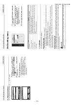
Push t
h
e [
Lit
e
-V
is
ion
plus Remot
e
C
ontro
ll
er
Installation
Manual
∧
] /
[
∨
] button t
o
select
“
1. Test Mode
” on
the “
Fi
e
ld s
e
tting menu
sc
reen, then push
the “
Set” [
F2] button.
Æ
Pu
s
h
in
g the
“
Yes” [
F1] bu
tton
sets th
e test m
ode a
nd the
sc
re
e
n
re
tur
n
s to the
field se
ttin
g
m
enu scr
een.
Pu
s
h
[
CANCEL
] twice
, the
s
c
reen
(2
)
ap
pear
s.
2
Push the
[
ON
/
OFF
]
button
to start the
test mode.
The screen
(1)
shown in
the
le
ft
appear
s. (The screen
(2)
appears
when t
h
e
operatio
n i
s
sto
pped.)
Æ
Pe
rfo
rm
the t
est mo
de in th
e “
C
o
ol”
or
“
H
e
at”
m
ode.
Æ
Tem
per
atur
e s
e
tting c
a
nnot be adjusted
dur
ing
th
e test mode
.
Æ
Check code
s ar
e displayed a
s
usual.
3
W
h
en the
test
m
ode is f
inished,
push the
[
∧
] / [
∨
] button to
s
e
lect
“
1. Test
Mode
”
on the “
Fi
eld setting me
n
u
” scre
e
n,
then push
the “
Set”
[
F2
]
button.
The screen
(3)
appear
s.
Æ
Pu
s
h
in
g the
“
Yes” [
F1] bu
tton
stop
s the te
st mo
de scre
en a
nd con
tin
ues the
no
rm
al ope
rat
io
n.
NOTE
Th
e t
e
st
mo
de
sto
p
s a
fte
r 6
0
minu
te
s an
d
the
scr
ee
n
re
tur
n
s t
o
t
he
no
rm
al /
det
ailed
d
is
p
lay
.
1
.T
est mode
2
.Register service info.
3
.Alarm history
4
.Monitor function
5
.DN setting
Field setting menu
Return
Set
Set
Ye
s
Return
T
est mode start.
No
Ye
s
T
est mode
T
est
(1)
Room A
12:00
Mode
Fan Speed
Cool
Set
Ye
s
T
est
(2)
Room A
12:00
Return
T
est mode stop.
No
Ye
s
T
est mode
(3)
Lit
e
-V
is
ion
plus Remot
e
C
ontro
ller
Installation
Manual
Usi
n
g the
Service moni
tor
w
ith the [
M
O
NI
TO
R]
b
u
tt
o
n
durin
g
th
e test mo
de
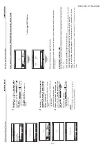
2.
Re
gister servic
e
info
Register
infor
m
at
io
n abo
ut the
conta
c
t num
ber
for
ser
v
ic
e,
mod
el
nam
e and
serial n
umb
er
of the
in
door
un
it
and
out
door
un
it.
•
Enter
infor
m
a
tion m
anua
lly for
a
Lig
h
t com
m
e
rcial outd
oor
unit.
Infor
m
a
tio
n data
o
f Light com
m
er
cial
ind
oor
unit, mu
lti
indoo
r un
it,
a
nd VRF ou
tdoor
unit is lo
aded a
u
tom
a
tically.
Autom
a
tic loading
is n
o
t availabl
e for s
o
me mod
e
ls. In
this
case, enter
info
rm
ation
m
anu
ally.
•
Enter
the
contact
numb
e
r for
ser
v
ice d
isplaye
d in “
2
. Ser
v
ice infor
m
a
tio
n”
of “
11. inf
o
rm
ation”
on
the
menu
s
c
reen
.
•
Enter
the
mod
e
l nam
e an
d ser
ia
l
numb
e
r displayed in “
1
. M
ode
l inf
o
rm
ation”
of
“1
1. infor
m
a
tion”
on t
he m
enu
s
c
reen
.
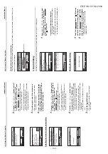
Push the [
MON
ITO
R] button
Ref
e
r to “
4
. Mo
nito
r fu
nc
tion
” (
pa
ge
26
) fo
r d
e
ta
ils.
Wh
en th
e gr
oup
c
o
ntr
o
l is
u
s
ed, select t
he un
it
to m
onitor
in the
unit selection
sc
reen
befo
re
dis
p
la
yin
g
the
m
o
nitori
n
g
display.
T
est
Room A
12:00
Mode
Fan Speed
Cool
Code
00
Data
0024
Return
Monitor function
FILE NO. SVM-
12004
–
107
–
Содержание RAV-SM307KRTP-A
Страница 14: ...RAV SM806KRT E TR FILE NO SVM 12004 14 ...
Страница 112: ...TOSHIBA CARRIER CORPORATION ...


