– 56 –
Wiring connection
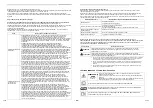
Indoor / Outdoor connecting wires specifications
Indoor unit power supplied from outdoor unit
• The outdoor unit power supply patterns vary on models.
*Number of wire × wire size
*Including earth line
Remote controller wiring
* 1 For detail of the wired remote controller (RBC-AMS55E*), follow the Installation Manual attached with the
remote controller.
CAUTION
The remote controller wire and Indoor / Outdoor connecting wires cannot be parallel to contact each other and cannot
be stored in the same conduits. If doing so, a trouble may be caused on the control system due to noise or other factor.
Indoor unit power supply
1~50 Hz 220 - 240 V
1~60 Hz 220 V
Indoor / Outdoor connecting wires*
4 × 1.5 mm
2
or more (H07 RN-F or 60245 IEC 66)*
Up to 70 m
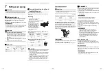
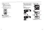
Remote controller wiring, remote controller inter-unit wiring
Wire size: 2 × 0.5 to 2.0 mm
2
Total wire length of remote controller wiring and remote
controller inter-unit wiring = L + L1 + L2 + … Ln
In case of wired type only
Up to 500 m
In case of wireless type included
Up to 400 m *1
Total wire length of remote controller inter-unit wiring = L1 + L2 + … Ln
Up to 200 m
L1
L
L2
Ln
Indoor unit
Remote controller inter-unit wiring
Indoor unit
Indoor unit
Indoor unit
Remote
controller
(Max. 8 units)
Remote
controller
wiring
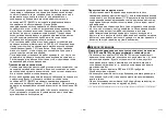
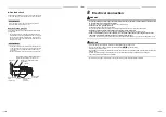
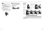
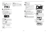
Wire connection
REQUIREMENT
• Connect the wires matching the terminal numbers. Incorrect connection causes.
• Pass the wires through the bushing of wiring connection port of the indoor unit.
• Keep a margin (Approx. 100mm) on a wire to hang down the electrical control box at servicing, or other purpose.
• The low-voltage circuit is provided for the remote controller. (Do not connect the high-voltage circuit)
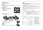
• Before remove the electric parts cover, remove the cover plate and air filter.
• Remove the cover of the electrical control box by taking off the mounting screws (2 positions) and pushing the hooking
section. (The cover of the electrical control box remains hanged to the hinge.)
• Tighten the screws of the terminal block, and fix the wires with cord attached to the electrical control box.
(Do not apply tension to the connecting section of the terminal block.)
• Set a loop for the connecting wire of the storing part of the indoor unit electric parts; otherwise the electrical control box cannot
be drawn out in service time.
• Mount the cover of the electrical control box without pinching wires.
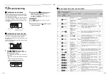
1 2 3
A B
Side D (Space: 8.5 mm)
Side C (Space: 4 mm)
Select side C or D for the power cable
clamping position referring to the following
table according to the cable type and
diameter.
* Cable clamp can be attached on either
right or left side.
When twin system are connected, clamp two
cables with one cable clamp.
Wire
type
Specification
Cable clamping
position
Cabtyre
cable
4-core stranded
wire 2.5 mm²
Side D
Cabtyre
cable
4-core stranded
wire 1.5 mm²
Side C
Power supply
terminal block
Remote controller
terminal block
Cord clamp
Air filter
Electrical control box
Electrical control box cover
Screw
(2 positions)
Cover plate
Earth
111-EN
112-EN
Содержание RAV-RM301SDT-E
Страница 68: ...EB99819301 ...

