background image

– 28 –

Item

2. Indoor fan

motor control

Operation flow and applicable data, etc.

<In cooling operation>

(This operation controls the fan speed at indoor unit side.)

The indoor fan (cross flow fan) is operated by the phase-
control induction motor. The fan rotates in 5 stages in
MANUAL mode, and in 5 stages in AUTO mode, respec-
tively. (Table 1)

Description

* Symbols

UH

: Ultra High

H

: High

M+

:

M

: Medium

L+

: Low+

L

:  Low

L-

: Low–

UL

: Ultra Low

SUL

: Super Ultra Low

* The fan speed broadly varies due

to position of the louver, etc.
The described value indicates one
under condition of inclining
downward blowing.

1) When setting the fan speed to L,

L+, M, M+ or H on the remote
controller, the operation is
performed with the constant
speed shown in Fig. 1.

2) When setting the fan speed to

AUTO on the remote controller,
revolution of the fan motor is
controlled to the fan speed level
shown in Fig. 2 and Table 1
according to the setup tempera-
ture, room temperature, and heat
exchanger temperature.

(Fig. 1)

(Fig. 2)

+2.5

Ta

[˚C]

+2.0

+1.5

+1.0

+0.5

Tsc

a

b

c

d

e

M+(WB)

*3

*4

*5

L(W6)

Air volume AUTO

L

L+

M

M+

H

W6

(L + M) / 2

W9

(M + H) / 2

WC

Indication

Fan speed

Fan speed setup

COOL ON

AUTO

MANUAL

*3 : Fan speed = (M + –L) x 3/4 + L

*4 : Fan speed = (M + –L) x 2/4 + L

*5 : Fan speed = (M + –L) x 1/4 + L

(Linear approximation 
from M+ and L)
 

(Table 1)  Indoor fan air flow rate

Fan speed

level

Fan speed Air flow rate Fan speed Air flow rate Fan speed Air flow rate Fan speed

Air flow rate

(rpm)

(m3/h)

(rpm)

(m3/h)

(rpm)

(m3/h)

(rpm)

(m3/h)

WF

UH

1240

630

1240

630

1240

630

1470

743

WE

H

1170

582

1170

582

1240

630

1470

743

WD

UH

M+

UH

1140

563

1140

563

1190

596

1440

723

WC

H

H

1100

536

1100

536

1140

563

1390

691

WB

M+

M+

M+

1000

469

1000

469

1040

496

1250

601

WA

M 1000

469

1000

469

100

469

1190

563

W9

M L+

960

443

960

443

960

443

1120

518

W8

L 870

383

870

383

870

383

970

421

W7

L+

L-

L+

850

369

850

369

850

369

950

408

W6

L L 

760

309

760

309

760

309

890

370

W5

L-

UL

L-

760

309

760

309

760

309

870

357

W4

UL

UL

700

269

700

269

700

269

810

318

W3

SUL

SUL

650

236

650

236

650

236

750

280

W2

SUL

500

135

500

135

500

135

600

183

W1

500

135

500

135

500

135

500

119

   RAS-M13SKV-E    

RAS-M13SKCV-E

   RAS-M16SKV-E    

RAS-M16SKCV-E

RAS-M07SKV-E

DRY

HEAT

COOL

   RAS-M10SKV-E    

RAS-M10SKCV-E

Revised-2

Содержание RAS-M07SKV-E

Страница 1: ...E NO SVM 07034 2 SERVICE MANUAL SPLIT TYPE Indoor Unit High Wall Heat PumpType RAS M07SKV E Revised May 2009 High Wall CoolingType RAS M10SKCV E RAS M13SKCV E RAS M16SKCV E RAS M10SKV E RAS M13SKV E RAS M16SKV E ...

Страница 2: ...N VIEWS 16 5 WIRING DIAGRAM 17 6 SPECIFICATIONS OF ELECTRICAL PARTS 19 7 REFRIGERANT CYCLE DIAGRAM 20 8 CONTROL BLOCK DIAGRAM 21 9 OPERATION DESCRIPTION 23 10 INSTALLATION PROCEDURE 47 11 HOW TO DIAGNOSE THE TROUBLE 55 12 HOW TO REPLACE THE MAIN PARTS 74 13 EXPLODED VIEWS AND PARTS LIST 83 ...

Страница 3: ...in unit and installation tools are different from those used for the conventional refrigerant units Accordingly special tools are required for the new refrigerant R410A units For connecting pipes use new and clean piping materials with high pressure fittings made for R410A only so that water and or dust does not enter Moreover do not use the existing piping because there are some problems with pre...

Страница 4: ...a qualified electrician in accordance with the Installation Manual Make sure the air conditioner uses an exclusive circuit An insufficient circuit capacity or inappropriate installation may cause fire When wiring use the specified cables and connect the terminals securely to prevent external forces applied to the cable from affecting the terminals Be sure to provide grounding Do not connect ground...

Страница 5: ...bes about M SKV E series indoor units RAS M07SKV E RAS M10SKV E RAS M13SKV E RAS M16SKV E RAS M10SKCV E RAS M13SKCV E and RAS M16SKCV E only For the multi outdoor unit to be combined refer to the service manual A06 013 A05 014 1 A06 014 A05 011 1 RAS M14GAV E RAS M18GAV E Combined outdoor unit Indoor unit model name Combined outdoor unit model name Indoor unit model name model name RAS 3M18SAV E R...

Страница 6: ...dditional refriderant Maximum height difference m Name of refrigerant Weight kg Wiring connection Power supply Interconnection Usable temperature range Indoor Cooling Heating Outdoor Cooling Heating Accessory Indoor unit Installation plate Wireless remote control Remote control holder Pan head wood screw Super Oxi Deo filter Super Sterilizer filter Battery Mounting screw Owner s manual Installatio...

Страница 7: ...mum length per unit m 1 Minimum length per unit m 1 Maximum length total m 1 Maximum chargeless length m 1 Additional refriderant 1 Maximum height difference m 1 Name of refrigerant R410A Weight kg 1 Wiring connection Power supply 3 Wires includes earth Interconnection 4 Wires includes earth Usable temperature range C Indoor Cooling Heating 21 32 Outdoor Cooling Heating 1 Accessory Indoor unit Ins...

Страница 8: ... pressure in the refrig eration cycle may become abnormally high so that a rupture or personal injury may be caused 5 After completion of installation work check to make sure that there is no refrigeration gas leakage If the refrigerant gas leaks into the room coming into contact with fire in the fan driven heater space heater etc a poisonous gas may occur 6 When an air conditioning system charged...

Страница 9: ...s of socket joints Nominal diameter 1 4 3 8 1 2 5 8 Reference outer diameter of copper pipe jointed mm 6 35 9 52 12 70 15 88 Minimum joint thickness mm 0 50 0 60 0 70 0 80 3 2 2 Processing of Piping Materials When performing the refrigerant piping installation care should be taken to ensure that water or dust does not enter the pipe interior that no other oil than lubricating oils used in the inst...

Страница 10: ...tch type 0 to 0 5 0 to 0 5 0 to 0 5 0 to 0 5 Conventional flare tool Clutch type Wing nut type 1 0 to 1 5 1 5 to 2 0 1 0 to 1 5 1 5 to 2 0 1 0 to 1 5 2 0 to 2 5 1 0 to 1 5 2 0 to 2 5 Table 3 2 4 Dimensions related to flare processing for R22 Nominal diameter 1 4 3 8 1 2 5 8 Outer diameter mm 6 35 9 52 12 70 15 88 Thickness mm 0 8 0 8 0 8 1 0 A mm Flare tool for R22 clutch type 0 to 0 5 0 to 0 5 0 ...

Страница 11: ...ghtening torque for R410A is the same as that for conventional R22 Incidentally when the torque is weak the gas leakage may occur When it is strong the flare nut may crack and may be made non removable When choosing the tighten ing torque comply with values designated by manufacturers Table 3 2 7 shows reference values NOTE When applying oil to the flare surface be sure to use oil designated by th...

Страница 12: ... refrigerant charging Refrigerant cylinder Leakage detector Charging cylinder Usage Pipe flaring Flaring by conventional flare tool Connection of flare nut Evacuating refrigerant charge run check etc Vacuum evacuating Refrigerant charge Refrigerant charge Gas leakage check Refrigerant charge R410A air water heat pump installation Existence of new equipment for R410A Yes Yes Yes Yes Yes Yes Yes Yes...

Страница 13: ...and the connecting port of the electronic balance and charge liquid refrigerant Water heat exchanger unit Outdoor unit Opened Opened Refrigerant cylinder with siphon Check valve Open close valve for charging Electronic balance for refrigerant charging Opened Closed Service port 3 4 Recharging of Refrigerant When it is necessary to recharge refrigerant charge the specified amount of new refrigerant...

Страница 14: ... composed of silver and copper It is used to join iron copper or copper alloy and is relatively expensive though it excels in solderability 2 Phosphor bronze brazing filler Phosphor bronze brazing filler is generally used to join copper or copper alloy 3 Low temperature brazing filler Low temperature brazing filler is generally called solder and is an alloy of tin and lead Since it is weak in adhe...

Страница 15: ...ore use a flux which does not contain chlorine 3 When adding water to the flux use water which does not contain chlorine e g distilled water or ion exchange water 4 Remove the flux after brazing 3 5 3 Brazing As brazing work requires sophisticated techniques experiences based upon a theoretical knowledge it must be performed by a person qualified In order to prevent the oxide film from occurring i...

Страница 16: ...2 7mm 116 Air inlet Air filter Heat exchanger 275 790 Wireless remote controller 56 Front panel Knock out system Knock out system 48 7 63 19 157 Installation plate outline Center line Hanger Hanger Hanger 621 170 or more 170 or more 65 or more Minimum distance to wall Minimum distance to wall Minimum distance to ceiling 16 4 CONSTRUCTION VIEWS RAS M07SKV E RAS M10SKV E RAS M13SKV E RAS M16SKV E RA...

Страница 17: ... 17 5 WIRING DIAGRAM 5 1 RAS M07SKV E RAS M10SKV E RAS M13SKV E RAS M10SKCV E RAS M13SKCV E Revised 2 ...

Страница 18: ...5 2 RAS M16SKV E RAS M16SKCV E 18 Revised 2 ...

Страница 19: ...or M16SKV E M16SKCV E DC 340V 30W 2 Room temp sensor TA sensor 10kΩ at 25 C 3 Heat exchanger temp sensor TC sensor 10kΩ at 25 C 4 Louver motor Output Rated 1W 16 poles DC12V MP24Z3T AFS 220 20 4AR AC240V 20W Parts name 1 ICF 340 30 2B Specifications Type M13SKV E M10SKCV E M13SKCV E Revised 2 ...

Страница 20: ...ent TC TA Indoor heat exchanger Cross flow fan Deoxidized copper pipe Outer dia 6 35mm Thickness 0 8mm Sectional shape of heat insulator Allowable height difference 10m Allowable pipe length P Pressure measurement Gauge attaching port Vacuum pump connecting port Min 1 Chargeless 1 Max 1 Charge 1 TCJ M16SKV E M16SKCV E Deoxidized copper pipe Outer dia 12 7mm Thickness 0 8mm Revised 2 ...

Страница 21: ...ply Circuit Infrared Rays 36 7kHz Remote Controller Thermo Setting Fan Speed Selection ON TIMER Setting OFF TIMER Setting Louver AUTO Swing Louver Direction Setting QUIET Operation Mode Selection AUTO COOL DRY HEAT REMOTE CONTROLLER ECO Hi POWER Heat Exchanger Sensor Tc Room Temperature Sensor Ta Infrared Rays Signal Receiver and Indication Functions Cold draft preventing Function 3 minute Delay a...

Страница 22: ...and Information Serial Signal Transmitter Receiver Converter D C circuit Noise Filter Indoor Fan Motor Louver Motor Louver Motor Drive Control Indoor Fan Motor Control Initializing Circuit Clock Frequency Oscillator Circuit Power Supply Circuit Room Temperature Sensor Ta Infrared Rays Signal Receiver and Indication Functions Cold draft preventing Function 3 minute Delay at Restart for Compressor F...

Страница 23: ...tion status meets to the operation command signal Whether protective circuit operates When no signal is received from the outdoor unit controller it is assumed as a trouble motor drive circuit is mounted to the indoor unit The compressor and the inverter to control fan motor are mounted to the outdoor unit The entire air conditioner is mainly controlled by the indoor unit controller The indoor uni...

Страница 24: ...34 8 Self Cleaning function 35 9 Selt Cleaning function release 36 10 Remote A or B selection 37 9 3 Auto Restart Function 40 9 3 1 How to Set the Auto Restart Function 40 9 3 2 How to Cancel the Auto Restart Function 41 9 3 3 Power Failure During Timer Operation 41 16 FILTER Indicator 39 9 4 Remote Controller and Its Fuctions 42 9 4 1 Parts Name of Remote Controller 42 9 4 2 Operation of remote c...

Страница 25: ...l contents of remote controller ON OFF Operation select Temperature setup Air direction Swing Air volume select AUTO LOW LOW MED MED HIGH ECO ON timer setup OFF timer setup Hi POWER Indoor unit control Command signal generating function of indoor unit operation Calculation function temperature calculation Activation compensation function of indoor fan Cold draft preventive function Timer function ...

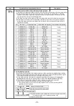
Страница 26: ...ned off and it is turned on during defrost operation Only in heating No Indoor unit Set operating mode Actual indoor unit operation Actual outdoor unit operation Pressed first Cooling dry Cooling dry Pressed last Cooling dry Cooling dry Pressed first Heating Heating Pressed last Heating Heating Pressed first Fan only Fan only Pressed last Fan only Fan only Pressed first Fan only Fan only Pressed l...

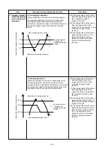
Страница 27: ...cording to the temperature difference between the room tempera ture and the setup temperature Tsc Setup temperature Tsc Set temperature on remote controller Ts 0 0 to 1 0 3 When the room temperature is lower 1 C or less than the setup temperature turn off the compressor 1 Detects the room temperature Ta when the operation started 2 Selects an operation mode from Ta in the left figure 3 Fan operati...

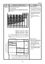
Страница 28: ...a C 2 0 1 5 1 0 0 5 Tsc a b c d e M WB 3 4 5 L W6 Air volume AUTO L L M M H W6 L M 2 W9 M H 2 WC Indication Fan speed Fan speed setup COOL ON AUTO MANUAL 3 Fan speed M L x 3 4 L 4 Fan speed M L x 2 4 L 5 Fan speed M L x 1 4 L Linear approximation from M and L Table 1 Indoor fan air flow rate Fan speed level Fan speed Air flow rate Fan speed Air flow rate Fan speed Air flow rate Fan speed Air flow ...

Страница 29: ...A C b 0 5 c 1 0 d 1 5 e 2 0 f 2 5 g 5 0 5 5 L W9 M WD 1 2 3 H WE H WE Line approximate H and SUL with Tc SUL W2 Stop 46 46 Tc 34 45 45 33 33 33 21 32 32 20 A 4 A 4 A 4 A 4 A 4 A 4 Fan speed MANUAL in starting Fan speed AUTO in stability Fan speed AUTO in starting L L M M H W8 L M 2 WA M H 2 WE Indication Fan speed Fan speed setup HEAT ON AUTO YES NO MANUAL TC 42 C Min air flow rate control Tc 52 5...

Страница 30: ...e motor winding with operation of the compressor 4 According to the difference resulted from comparison of the correction value of Hz signal with the present operation Hz the inverter output and the commuta tion timing are varied 5 Change the compressor motor speed by outputting power to the compressor The contents of control operation are same in cooling operation and heating operation About Curr...

Страница 31: ...C the compressor speed is kept Q zone When temperature of the indoor heat exchanger drops in the range from 46 C to under 55 C the compressor speed is kept Q zone 2 When temperature of the indoor heat exchanger rises to 55 C or higher the compressor speed is reduced P zone 3 When temperature of the indoor heat exchanger does not rise to 50 C or when it drops below to 46 C the capacity control oper...

Страница 32: ... exceeds either upper or lower limit position swing operation is performed in width 35 from the limit which the stop position exceeded 3 Swing 2 Louver position in heating operation 2 Air direction adjustment The position is automatically controlled according to the operation The set louver position is stored in memory by the microcomputer The angle of the louver is indicated as the louver closes ...

Страница 33: ...ne aHz B zone a to cHz C zone cHz 0 0 5 1 0 1 5 2 0 2 5 3 0 4 0 5 0 6 0 7 0 8 0 9 0 10 0 11 0 Room temp Set temp 3 5 3 0 2 5 1 5 1 0 TSC 1 0 2 0 5 5 1H 2H 11 10 7 6 5 4 3 2 1 OFF Dry Max 12 11 9 8 10 TA 6 0 6 5 3H 4H 5 0 4 5 4 0 2 0 0 5 0 5 12 9 8 Time Zone Frequency FAN Min Hz Fan speed depend on presetting and can change every speed 1 The control target temperature increase 0 5ºC per hour up to ...

Страница 34: ... Pi Pi Pi sound is heard and AUTO RESTART control is changed 3 When keeping RESET button pressed for 10 seconds or more Pi sound is heard and the temporary COOL operation starts 4 If the filter lamp goes on press RESET button to go off the filter lamp and then press RESET button again 5 To stop the temporary operation press the button again Filter lamp ON Press RESET button Did you press RESET but...

Страница 35: ...on of the operation performed prior to the reception of the stop code 3 After the Self Cleaning operation has been performed for the specified period the unit stops operating Unit now performing cooling or dry operation Press STOP button Only timer indicator lights and Self Cleaning operation starts Time set now elapses Operation stops function During Self Cleaning operations The louver opens slig...

Страница 36: ...s pressed but keep holding it continue The will beep 3 times in the first 3 seconds but it is not related to Self Cleaning function After holding about 20 seconds the air conditioner will beep 5 times without any blinking of display The Self Cleaning Operation had been cancelled Remark Presetting of Self Cleaning function above AUTO How to set Self Cleaning function To set the Self Cleaning functi...

Страница 37: ...the factory the remote controller selection is set to A on all the indoor units There is no A setting display Setting the remote controller To separate using of remote control for each indoor unit in case of 2 air conditioner are installed nearly Remote Control B Setup 1 Press RESET button on the indoor unit to turn 2 Point the remote control at the indoor unit 3 Push and hold CHK button on the Re...

Страница 38: ...SLEEP button to choose the operating hours Repeat pressing to select the hours If the COMFORT SLEEP button is pressed again means cancel comfort sleep mode Heating mode The preset temperature will drop down as show on ECO operation Item No 9 choose the operating hours Repeat Press the COMFORT SLEEP button to pressing to setect thehours If the COMFORT SLEEP button is pressed again means cancel comf...

Страница 39: ... 3 Target temperature is 24ºC 4 Louver position is set as stored position of the operating mode 5 Fan is controlled as followings Mode POWER mark is indicated on the display of the remote controller and the unit operates as follows 1 Automatic operation The indoor unit operates in according to the current operation 2 Cooling operation remote controller does not change The indoor unit s fan speed l...

Страница 40: ...r unit is equipped with an automatic restarting function which allows the unit to restart operating with the set operating conditions in the event of a power supply being accidentally shut down The operation will resume without warning three minutes after power is restored This function is not set to work when shipped from the factory Therefore it is necessary to set it to work 9 3 1 How to Set th...

Страница 41: ...is time press RESET button once more or use the remote controller to turn it on 9 3 2 How to Cancel the Auto Restart Function To cancel auto restart function proceed as follows Repeat the setting procedure the unit receives the signal and beeps three times The unit will be required to be turned on with the remote controller after the main power supply is turned off When the system is on stand by n...

Страница 42: ...onsumer preferences in your region of the world The coutomised settings control temperature air flow strength air flow direction and other settings to provide you alternate contact with ONE TOUCH OF THE BUTTON If you prefer other settings you can select from the many other operation functions of your Toshiba unit Press ONE TOUCH Start the operaton 2 AUTOMATIC OPERATION To automatically select cool...

Страница 43: ...scharged remote control Pressing the RESET button the unit can start or stop without using the remote control Operation mode is set on AUTOMATIC operation preset temperature is 24 C and fan operation is automatic speed 8 TIMER OPERATION Setting the ON Timer Setting the OFF Timer Press ON Set the desired ON timer Press OFF Set the desired OFF timer Press SET Set the timer Press SET Set the timer Pr...

Страница 44: ...ATION lamp does not blink 11 QUIET OPERATION To operate at super low fan speed for quiet operation except in DRY mode Press QUIET Start and stop the operation Note Under certain conditions QUIET operation may not provide adequate cooling or heating due to low sound features 12 COMFORT SLEEP OPERATION To save energy while sleeping automatically control air flow and automatically turn OFF Press COMF...

Страница 45: ...e mark is shown when holding down the button for more than 3 seconds while the mark is flashing Press another button to turn off the mark 8 ECO indicator Indicates when the ECO is in activated Press the ECO button to start and press it again to stop operation 9 A B change indicator remote controller When the remote controller switching function is set B appears in the remote controller display Whe...

Страница 46: ...ever if temperature of the indoor heat exchanger becomes over 55 C or more in B room the indoor fan stops the intermittent operation and starts continuous operation While heating operation is executed in two rooms if room temperature reached the setup temperature in both room nad thermo off occurred both indoor units start intermittent operation of the indoor fan Operated with setup number of revo...

Страница 47: ...door unit for better operation For the rear left and left piping Wall Make sure to run the drain hose sloped downward Do not allow the drain hose to get slack Cut the piping hole sloped slightly The auxiliary piping can be connected to the left rear left rear right right bottom right or bottom left Right Rear right Bottom right Rear left Bottom left Left 8 mm thick heat resisting polyethylene foam...

Страница 48: ...ntrol holder 1 Part No Part name Q ty Mounting screw Ø4 25L 6 Remote control holder mounting screw Ø3 1 16L 2 Others Name Owner s manual Installation manual Important information and warning B W strips Energy efficiency labels Part No P R E S E T ONE T OUC H QUIE T S WING T IME R ON F IL T E R C HK C L OC K OF F C L R S L E E P S E T F IX Hi P OWE R E C O C OMF OR T S L E E P MODE T E MP F A N Sup...

Страница 49: ... and port size have been changed to 1 2 UNF 20 threads per inch When purchasing a charge hose be sure to confirm the port size As pressure is high and gasification speed is fast it is difficult to read the indicated value by means of charging cylinder as air bubbles occur The size of opposite sides of flare nuts have been increased Incidentally a common wrench is used for nominal diameters 1 4 and...

Страница 50: ...ect sunlight or close to a heating source such as a stove Keep the remote controller at least 1 m away from the nearest TV set or stereo equipment This is necessary to prevent image disturbances or noise interference The location of the remote controller should be determined as shown below Fig 10 3 1 10 3 2 Drilling a Hole and Mounting Instal lation Plate Drilling a hole When install the refrigera...

Страница 51: ...use of the air conditioner NOTE Wire type More than 1 5 mm2 H07RN F or 60245IEC66 CAUTION This appliance can be connected to a main circuit breaker in either of the following two ways 1 Connection to fixed wiring A switch or circuit breaker which discon nects all poles and has a contact separa tion of at least 3 mm must be incorporated in the fixed wiring An approved circuit breaker or switch must...

Страница 52: ...slit on the bottom left or side of thefront panel for the bottom left or right connection with a pair of nippers 2 Changing drain hose For left connection left bottom connection and rear left connection s piping it is necessary to relocate the drain hose and drain cap CAUTION Earth line Connecting cable about 15 cm Connecting cable Screw Screw Earth line Terminal block Screw Cord clamp Terminal co...

Страница 53: ...they are posi tioned within 43 mm above the wall surface If the connecting pipes are positioned more than 43 mm above the wall surface the indoor unit may be unstable When bending the connecting pipe make sure to use a spring bender to avoid crushing the pipe Refer to the table below for the bending radius of each connection pipe Fig 10 3 17 NOTE If the pipe is incorrectly bent the indoor unit may...

Страница 54: ...s firmly hooked on the installation plate Installation plate Indoor unit Connecting cable Auxiliary pipes 10 3 7 Drainage 1 Run the drain hose at a downward sloped angle NOTE Hole should be made at a slight downward slant on the outdoor side Fig 10 3 21 2 Put water in the drain pan and make sure that the water is being drained outside 3 When connecting extension drain hose insulate the connection ...

Страница 55: ...of compressor motor speed stops approx 30 seconds after operation started and then compressor motor speed increases again approx 30 seconds after In AUTO mode the operation mode is changed In HEAT mode the compressor motor speed does not increase up to the maxi mum speed or decreases before the temperature arrives at the set temperature Description The OPERATION lamp of the indoor unit flashes whe...

Страница 56: ...hen air conditioner operates 2 When item B and C and item B and a part of item E occur concurrently priority is given to the block of item B 3 The check codes can be confirmed on the remote controller for servicing OPERATION Green Flashing display 1 Hz OPERATION Green TIMER Yellow FILTER Orange Flashing display 5 Hz OPERATION Green FILTER Orange Flashing display 5 Hz OPERATION Green TIMER Yellow F...

Страница 57: ...ep once Beep and the display of the remote controller will change as follows The TIMER indicator of the indoor unit flashes continuously 5 times per 1 sec Check the unit with all 52 check codes to as shown in Table 11 4 1 Press ON or OFF button to change the check code backward If there is a fault the indoor unit will beep for 10 seconds Beep Beep Beep Note the check code on the display of the rem...

Страница 58: ...rocomputer returns the initial status However the check codes are not deleted even if the power supply is turned off because they are stored in the fixed memory 3 After servicing press CLR button under check mode status and then send the check code 7F to the indoor unit The error code stored in memory is cleared Table 11 4 1 Block distinction Operation of diagnosis function Block Indoor P C board ...

Страница 59: ...k Outdoor P C board Not displayed Outdoor P C board Others including compressor Cause of operation Inverter over current protective circuit operates Short time Position detect circuit error or short circuit between windings of compressor Current detect circuit error Being out of place disconnection or short circuit of the outdoor heat exchanger sensor TE or suction temp sensor Ts Disconnection or ...

Страница 60: ...upply by pushing START STOP button on remote controller Is voltage DC12V or 5V indicated on rear of indoor control board normal Does transmission mark on remote controller flash normally and is its signal transmitted properly Item by symptoms Operation Check Item Considerable principle cause Measures Parts R01 C01 C02 R02 C03 D01 D02 D03 D04 Remote controller is defective Refer to 5 Troubleshootin...

Страница 61: ...smitted properly Is DC310 340V supplied between CN10 1 3 Does fan motor connector between CN10 1 3 short circuit Item by symptoms Operation Check Item Considerable principle cause Measures Parts R04 R05 DB01 C01 C03 IC01 and T01 are defective Remote controller is defective Refer to 5 Troubleshooting for remote controller Parts of a power supply circuit defective Unit operates normally Replace main...

Страница 62: ...flow fan by hand at the operation stop condition is the rotation signal DC 12V 0V detected between 2 Purple lead and 3 Blue lead of the motor connector CN33 1 pulse 1 revolutio Dose AC120V or ligher voltage apply to between red and black lead of the motor Is it possible to change airflow level to HIGH Stop the operation Does fan motor continue to operate Does indoor fan operate Fan motor operates ...

Страница 63: ...tor connector CN31 Check this condition within 15 seconds after starting unit Start to operate the indoor unit in except heating operation At this time is it possible to detect DC 1V or more between 5 and 3 of motor connector CN31 Is it possible to detect DC 1V or more between 5 and 3 of motor connector CN31 Is it possible to detect DC 310 340V between 1 and 3 of motor connector CN31 Motor connect...

Страница 64: ...or in RAS M16SKV E RAS M16SKCV E Cause The IC is built in the indoor fan motor Therefore the P C board is also mounted to inside of the motor If the P C board is soldered imperfectly or the IC is defective the fan motor may automatically rotate by turning on power supply Inspection procedure 1 Remove the front panel Remove 2 screws 2 Remove the cover of the fan motor lead wires 3 Check DC voltage ...

Страница 65: ...ble by Every Symptom AFS 220 20 4AR Do not disconnect the connector while the fan motor is rotating For P C board side proceed to the item Only indoor fan does not oper 1 3 5 1 2 3 2 1 3 2 1 3 2 1 3 2 1 3 CN31 CN33 P C board WHI BLK RED BLK RED WHI BLU PUR GRY BLU PUR GRY Resistance value Position P C board Between 3 Black 1 Red Between 3 Black 5 White Between 1 Red 5 White 74 15 Ω 100 20 Ω 174 35...

Страница 66: ... Batteries are exhausted Does radio sound is affected by remote controller when a signal is transmitted at distance of 5 cm from radio Is transmission mark indicated P C board is defective Replace P C board Replace batteries Replace remote controller Normal operation Remote controller is defective NO YES NO YES NO YES NO YES NO YES NO YES NO YES Does indoor unit start to operate by automatic resta...

Страница 67: ...transmission from indoor unit to outdoor unit is correctly performed based upon the follow ing diagram NOTE Measurement should be performed 2 minutes and 30 seconds after starting of the operation Be sure to prepare a diode for judgment Normal time Voltage swings between DC15 and 60V Inverter Assembly check 11 8 1 Abnormal time Voltage does not vary 2 Outdoor unit stops in a little while after ope...

Страница 68: ...C board hold the whole housing Do not pull at the lead wire 2 Inspection procedures 1 When a P C board is judged to be defective check for disconnection burning or discoloration of the copper foil pattern or this P C board 2 The P C board consists of the following 2 parts a Main P C board part DC power supply circuit Indoor fan motor control circuit CPU and peripheral circuits buzzer and Driving c...

Страница 69: ...ll indicators OPERATION TIMER FILTER PURE are lit for 3 seconds and they return to normal 3 seconds later 1 Check whether or not the com pressor operates 2 Check whether or not the OP ERATION indicator flashes 1 Check whether or not the com pressor operates 2 Check whether or not the OP ERATION indicator flashes 1 Check it is impossible to detect the voltage AC120V or higher voltage between red an...

Страница 70: ...Check whether or not all indicators OPERATION TIMER FILTER PURE are lit for 3 seconds and they return to normal 3 seconds later 1 Check whether or not the com pressor operates 2 Check whether or not the OP ERATION indicator flashes 1 Check whether or not the com pressor operates 2 Check whether or not the OP ERATION indicator flashes 1 Check it is impossible to detect the voltage DC 15V between 3 ...

Страница 71: ...0 40 50 60 70 80 90 20 10 0 0 10 20 30 40 50 Resistance value k Temperature C TA Room temp sensor TC Heat exchanger temp sensor TCJ Heat exchanger temp sensor TA TC TCJ 1 Sensor characteristic table 5V RAS M07 10 13 Series 71 Revised 2 ...

Страница 72: ...es 100 30 40 50 60 70 80 90 20 10 0 0 10 20 30 40 50 Resistance value k Temperature C TA Room temp sensor TC Heat exchanger temp sensor TCJ Heat exchanger temp sensor TA TC TCJ 1 Sensor characteristic table 12V GND 5V ...

Страница 73: ...mperature Sensor TCJ TA TC kΩ 10 C 20 C 25 C 30 C 40 C 20 7 12 6 10 0 7 9 4 5 5 4 3 2 1 White Yellow Yellow Yellow Yellow 5 4 3 2 1 Refer to 11 5 1 5 Measure the resistance value of each winding coil by using the tester Under normal temp 25 C Position 1 to 2 1 to 3 1 to 4 1 to 5 Resistance value 250 20Ω Refer to 11 5 1 3 and 4 2 3 Remote controller Louver motor MP24Z3T 4 Indoor fan motor sensor ...

Страница 74: ...he refrigerant gas 2 Do not use welding equipment in an airtight room Carbon monoxide poisoning may result if the room is not properly ventilated 3 Do not bring welding equipment near flammable objects Flames from the equipment may cause the flammable objects to catch fire If keeping the power on is absolutely unavoidable while doing a job such as inspecting the cir cuitry wear rubber gloves to av...

Страница 75: ...ow to assemble the front panel 1 Press three center positions and two lower center positions of the air outlet and then hang the hanging hooks 3 pcs at the top side of the front panel to the rear plate 2 Tighten two screws Incomplete hanging or incomplete pressing may cause a dewdrops or generation of a fluttering sound 2 Screws Three hooks ...

Страница 76: ...y and secure it using the fixing screw Now attach the display unit Connect the connectors for the fan motor and louver motor 2 Secure the grounding wire using the fixing screw Insert the TC sensor into the sensor holder Be absolutely sure to loop the grounding wire and TC sensor leads once at the bottom 6 Disengage the display unit by simply pushing at the top of the display unit 7 Remove the fixi...

Страница 77: ...he item k 2 Remove the pipe holder from the rear side of the main unit 3 Remove two fixing screws at the left side of the end plate of the heat exchanger Remarks 4 Remove one fixing screw on the heat exchage fixing holder to separate the heat exchage from the back body 5 Remove right side of the end plate from two fixing rib while sliding slightly the heat exchanger rightward 2 screws Heat exchang...

Страница 78: ... item m 2 Remove the two screws used to secure the bearing base 3 Remove the bearing base Caution at assembling If the bearing is out from the housing push it into the specified position and then incorporate it in the main body Remarks Two screws Bearing Bearing base n ...

Страница 79: ...the set screw of the cross flow fan 3 Remove two fixing screws of the motor cover and them remove the motor cover 4 Remove two more fixing screws of the motor band and remove the motor band Remarks 5 Pull the fan motor outward Set screw Two screws on motor band o Motor cover Two Screws ...

Страница 80: ...eeping 70 5 mm from wall of rear plate of the main unit Holding the set screw install the cross flow fan so that U groove of the fan motor comes to the mounting hole of the set screw Perform positioning of the fan motor as follows When assembling the fan motor the fan motor must be installed in such a way that the fan motor leads will be taken out is positioned at the bottom front After assembling...

Страница 81: ...conditioner 2 Remove the front panel Remove the 2 fixing screws 3 Remove the electrical part base Remarks Replace terminal block microcomputer ass y and the P C board ass y 12 2 Microcomputer P C board layout CN33 CN31 R02 R01 C01 FUSE L01 C02 C03 CN51 T01 IC12 C121 C133 RAS M07 10 13 Series Revised 2 ...

Страница 82: ... 82 R05 L01 C01 CN23 FUSE R04 R01 CN10 J04 IC03 C20 IC01 T01 C03 DB01 RAS M16 Series ...

Страница 83: ...T20325 CROSS FLOW FAN ASSEMBLY 219 43T44410 REFRIGERANT CYCLE ASSEMBLY 206 43T11301 PIPE SHIELD FOR RAS M16SKV E SKCV E FOR RAS M07 10 13SKV E SKCV E 221 43T00488 PANEL SERVICE ASSEMBLY 206 43T11320 PIPE SHIELD 222 43T80318 AIR FILTER R FOR RAS M16SKV E SKCV E 223 43T80319 AIR FILTER L 207 43T83003 REMOTE CONTROL HOLDER 224 43T09410 GRILLE OF AIR INLET ORIGINAL WHITE 208 43T60382 MOTOR CORD 226 43...

Страница 84: ...URE SENSOR 407 43T69672 PC BOARD FOR RAS M10SKV E 403 43T60002 TERMINAL BLOCK 3P 407 43T69673 PC BOARD FOR RAS M13SKV E 404 43T69320 TEMPERATURE SENSOR 407 43T69674 PC BOARD FOR RAS M10SKCV E 405 43T62003 CORD CLAMP 407 43T69675 PC BOARD FOR RAS M13SKCV E 406 43T69633 PC BOARD ASSY WRS LED 407 43T69826 PC BOARD FOR RAS M07SKV E 407 43T69670 PC BOARD FOR RAS M16SKV E Description Description ...

Страница 85: ... THAILAND CO LTD 144 9 MOO 5 BANGKADI INDUSTRIAL PARK TIVANON ROAD TAMBOL BANGKADI AMPHUR MUANG PATHUMTHANI 12000 THAILAND ...

Отзывы: