


– 65 –
10. INSTALLATION PROCEDURE
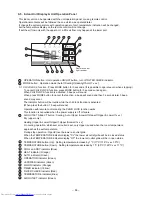
10-1. Installation Diagram of Indoor and Outdoor Units
(A)
(B)
(C)
(D)
Vinyl tape
Apply after carrying
out a drainage test.
600 mm or more only
when unobstructed
to the front and both
sides.
Extension
drain hose
(Not available,
provided by installer)
100
mm
or
mor
e
100
mm
or m
ore
60
0 mm
or
more
600
mm
or
mor
e
Saddle
1
Installation plate
50 mm or more
50 mm or more
Shield pipe
Air filter
5
Filter
5
Filter
70
mm
or
more
3
Batteries
7
Pan head
wood screw
4
Remote control holder
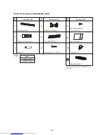
Remark :
•
Detail of accessory and installation
parts can see in the accessory sheet.
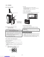
When installing the outdoor unit,
leave open in at least two of direction
(A), (B), (C) and (D) shown in the
fi
gure on the right.
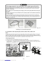
Do not allow the drain hose to get
slack.
Make sure to run the drain hose
sloped downward.
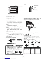
The auxiliary piping can be
connected to the left, rear left, rear
right, right, bottom right or bottom
left.
Cut the piping
hole sloped
slightly.
Right
Rear right
Left
Bottom right
Rear left
Bottom left
CAUTION
Install in rooms that are 13 m
3
or larger.
If a leak of refrigerator gas occurs
inside the room, an oxygen de
ficiency
can occur.
6
Mounting screw
8
Insulation sheet
2
Wireless remote control
8 mm thick heat resisting
polyethylene foam
Insulate the refrigerant pipes
separately with insulation, not together.
In case of right or left piping
cut dot-line area
A
C
L
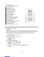
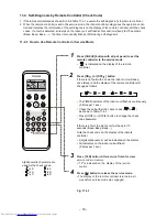
• Loading Batteries
1. Remove the battery cover.
2. Insert 2 new batteries (AAA type)
following the (+) and (–) positions.
Before installing the wireless remote controller
3 Batteries
2 Wireless remote controller
Содержание RAS-18SAV-E
Страница 17: ... 17 ...