background image

2

•  Secure the outdoor unit with 

fi

 xing bolts and nuts if the unit is likely to be 

exposed to a strong wind.

•  Use Ø8 mm or Ø10 mm anchor bolts and nuts.
•  If it is necessary to drain the defrost water, attach drain nipple 

9

 and cap 

water proof 

!

 to the bottom plate of the outdoor unit before installing it.

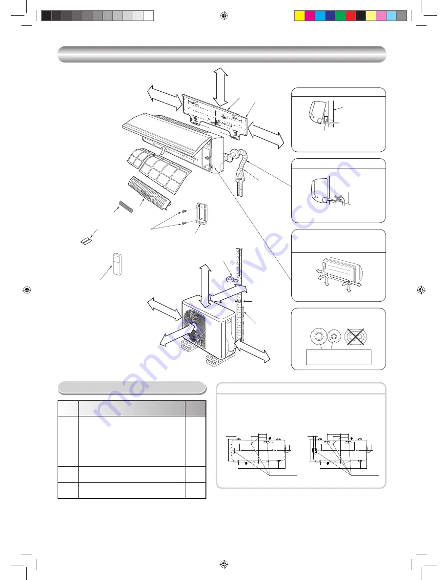
Fixing bolt arrangement of outdoor unit

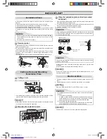
INSTALLATION DIAGRAM OF INDOOR AND OUTDOOR UNITS

INSTALLATION DIAGRAM OF INDOOR AND OUTDOOR UNITS

Part

code

Parts name

Q’ty

A

Refrigerant piping
Liquid side 

:  Ø6.35 mm

Gas side 

:  Ø9.52 mm


  (10, 13SKVP2 Series, 


  25, 35SKVP2 Series)

 : 

Ø12.7 

mm


(16SKVP2 

Series, 


45SKVP2 

Series)

One

each

B

Pipe insulating material
(polyethylene foam, 6 mm thick)

1

C

Putty, PVC tapes

One

each

Optional Installation Parts


Insulate the refrigerant pipes separately 
with insulation, not together.

2

3

8

6

4

Insert the cushion between the indoor 
unit and wall, and tilt the indoor unit for 
better operation.

For the rear left and left piping

Wall

Make sure to run the drain hose sloped 
downward.

Do not allow the drain hose to get slack.

Cut the piping 
hole sloped 
slightly.

The auxiliary piping can be connected to 
the left, rear left, rear right, right, bottom 
right or bottom left.

Right

Rear 
right

Bottom
right

Rear
left

Bottom left

Left

6 mm thick heat resisting
polyethylene foam

1

Batteries

Pan head
wood screw

Remote control holder

Vinyl tape
Apply after carrying
out a drainage test.

Wireless remote control

Saddle

Extension
drain hose
(Not available,
provided by installer)

Shield pipe

Filter

(Attach to the front panel.)

Air 

fi

 lter

Hook

Installation
plate

Hook

65 mm or more

170 mm or more

170 mm or more

600 mm or more

100 mm or more

100 mm or more

600 mm or more

600 mm or more

Remark :

•  Detail of accessory and installation parts can see in the accessory 

sheet.

•  Some pictures might be different from the actual parts.

5

Filter

Drain outlet

Air inlet

Air outlet

125 mm

108 mm

Ø25 mm

29 mm

330 mm

106 mm

121 mm

99 mm

600 mm

(10, 13, 16SAVP2 Series)

(25, 35, 45SAVP2 Series)

Drain outlet

Air inlet

Air outlet

125 mm

108 mm Ø25 mm

29 mm

330 mm

106 mm

121 mm

99 mm

600 mm

197 mm

1110251240-EN.indd   2

1110251240-EN.indd   2

4/19/11   2:07:19 PM

4/19/11   2:07:19 PM

Содержание RAS-16SAVP2 Series

Страница 1: ...AL Indoor unit RAS 10 13 16SKVP2 Series RAS 25 35 45SKVP2 Series Outdoor unit RAS 10 13 16SAVP2 Series RAS 25 35 45SAVP2 Series 1110251240 ENGLISH PУCСКИЙ TÜRKÇE Cover 1110251240 indd 1 Cover 1110251240 indd 1 4 5 11 5 19 47 PM 4 5 11 5 19 47 PM ...

Страница 2: ...onte edilmesi 4 İç Ünitenin Takılması 5 Su Boşaltma 5 DIŞ ÜNİTE 5 Montaj Yeri 5 Soğutma Maddesi Boru Bağlantısı 6 Boşaltma 6 Kablo Bağlantısı 7 DİĞERLERİ 7 Gaz Kaçağı Testi 7 Uzaktan Kumanda ile A B Seçimi 7 Test İşlemi 7 Otomatik Yeniden Başlama Ayarı 7 İÇİNDEKİLER TR MEPЫ БEЗOПACHOCTИ 1 СХЕМА УСТАНОВКИ ВНУТРЕННЕГО И НАРУЖНОГО БЛОКОВ 2 Oпционaльныe Уcтaновочныe Чacти 2 BHУTPEHHИЙ БЛOК 3 Mecто Уcт...

Страница 3: ...ting machine oil the sizes of charging port connecting sections on the main unit are different from those for the conventional refrigerant and different size tools are also required For connecting pipes use new and clean piping materials with highpressure withstand capabilities designed for R410A only and ensure that water or dust does not enter Moreover do not use any existing piping as its press...

Страница 4: ...hose sloped downward Do not allow the drain hose to get slack Cut the piping hole sloped slightly The auxiliary piping can be connected to the left rear left rear right right bottom right or bottom left Right Rear right Bottom right Rear left Bottom left Left 6 mm thick heat resisting polyethylene foam 1 Batteries Pan head wood screw Remote control holder Vinyl tape Apply after carrying out a drai...

Страница 5: ...es near the air inlet and outlet A place which allows easy installation of the piping to the outdoor unit A place which allows the front panel to be opened The indoor unit shall be installed as top of the indoor unit comes to at least 2 m height Also it must be avoided to put anything on the top of the indoor unit CAUTION 5 4 45 5 7 Side view Top view Indoor unit R e c e p t i o n r a n g e Remote...

Страница 6: ...n cut them with a pair of nippers or an equivalent tool Slit Slit Left hand connection with piping Bend the connecting pipe so that it is laid within 43 mm above the wall surface If the connecting pipe is laid exceeding 43 mm above the wall surface the indoor unit may unstably be set on the wall When bending the connecting pipe make sure to use a spring bender so as not to crush the pipe Bend the ...

Страница 7: ...TE The hole should be made at a slight downward slant on the outdoor side 50 mm or more Do not put the drain hose end into water Do not put the drain hose end in the drainage ditch Do not form the drain hose into a wavy shape Do not rise the drain hose Extension drain hose Inside the room Drain hose Shield pipe Arrange the drain pipe for proper drainage from the unit Improper drainage can result i...

Страница 8: ...e Flaring Be sure to use a vacuum pump with counter flow prevention function so that inside oil of the pump does not flow backward into pipes of the air conditioner when the pump stops If oil inside of the vacuum pump enters the air conditioner which use R410A refrigeration cycle trouble may result 1 Connect the charge hose from the manifold valve to the service port of the packed valve at gas sid...

Страница 9: ...6 1 5 mm2 or more NOTE Connecting cable Wire type More than H07RN F or 245 IEC66 1 0 mm2 or more Wrong wiring connection may cause some electrical parts burn out Be sure to comply with local cords on running the wire from indoor unit to outdoor unit size of wire and wiring method etc Every wire must be connected firmly This installation fuse 15A must be used for the power supply line of this air c...

Страница 10: ...Cover back 1110251240 indd 1 Cover back 1110251240 indd 1 4 5 11 5 19 32 PM 4 5 11 5 19 32 PM ...

Отзывы: