


– 87 –
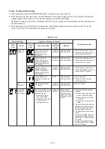
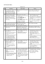
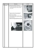
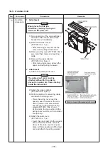
11-9-5. Checking Method for Each Part
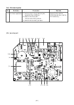
MCC-5009
Soldered
surface
Heat sink IGBT side
C12
C13
C14
Resistance value
in good product
∞
Tester rod
+
–
~
2
~
3
~
2
~
3
–
4
~
~
~
+
–
~
1
1 2 3
(DBO1)
4
4
2
3
+
1
+
–
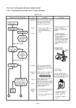
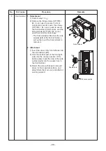
No.
1
2
Part name
Electrolytic capacitor
(For boost, smoothing)
Diode block
Checking procedure
1. Turn OFF the power supply breaker.
2. Discharge all three capacitors completely.
3. Check that safety valve at the bottom of capacitor is not broken.
4. Check that vessel is not swollen or exploded.
5. Check that electrolytic liquid does not blow off.
6. Check that the normal charging characteristics are shown in continuity test by
the tester.
Case that product is good
Pointer swings once, and returns
slowly. When performing test
once again under another polarity,
the pointer should return.
C12, C13, C14
→
500µF/400V
1. Turn OFF the power supply breaker.
2. Completely discharge the four electrolytic capacitors.
3. Remove the diode block from the PCB (which is soldered in place).
4. Use a multimeter with a pointer to test the continuity, and check that the
diode block has the proper rectification characteristics.
10 to 20
Ω
when the multimeter probe
is reversed
Содержание RAS-16SAVP-E
Страница 107: ... 107 MCC 5009 MCC 5009 04 F01 T25A 250V ...


