–
28
–
Item
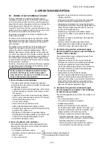
3. Outdoor fan
motor control
Operation flow and applicable data, etc.
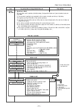
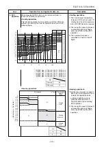
The blowing air volume at the outdoor unit side is controlled.
Receiving the operation command from the controller of
indoor unit, the controller of outdoor unit controls fan speed.
* For the fan motor, a DC motor with non-stage variable
speed system is used. However, it is limited to 8 stages for
reasons of controlling.
Description
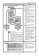
1) The operation command sent
from the remote controller is
processed by the indoor unit
controller and transferred to the
controller of the outdoor unit.
2) When strong wind blows at
outdoor side, the operation of air
conditioner continues with the
fan motor stopped.
3) Whether the fan is locked or not
is detected, and the operation of
air conditioner stops and an
alarm is displayed if the fan is
locked.
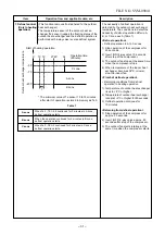
4) According to each operation
mode, by the conditions of
outdoor temperature (To) and
compressor revolution, the speed
of the outdoor fan shown in the
table is selected.
2) Fan speed
≥
400
when the motor stopped.
Air conditioner ON
(Remote controller)
YES
YES
NO
NO
Indoor unit controller
Fan motor ON
3) Fan lock
OFF status of
fan motor continues.
4) Motor operates as shown in the table below.
1) Outdoor unit
operation
command
(Outdoor
fan
control)
Air conditioner
OFF
Alarm
display
Outdoor fan speed (rpm)
Tap
f 1
f 2
f 3
f 4
f 5
f 6
f 7
f 8
200
300
370
440
440
500
550
600
Tap
f 9
f A
f B
f C
f D
f E
f F
650
700
700
800
800
800
800
Compressor speed (rps)
To
> 38°C
To > 28°C
To
To > 15°C
To > 5.5°C
To > 0°C
During
To > 38°C
ECO mode
To < 38°C
When To is abnormal
~ 13.8
~ 31.7
32.3 ~ MAX
MIN MAX MIN MAX MIN MAX
f 2
f 3
f A
f C
f D
f F
f 2
f 3
f 7
f A
f 9
f C
f 1
f 3
f 2
f 5
f 4
f 7
f 1
f 1
f 1
f 2
f 2
f 4
f 2
f 3
f B
f C f C
f D
In cooling operation
Compressor speed (rps)
To > 15
°
C
To
To < 15
°
C
To < 5.5
°
C
To <
−
5.0
°
C
To > 15
°
C
During To < 15
°
C
ECO mode
To < 5.5
°
C
To <
−
5.5
°
C
When To is abnormal
~16.8 ~47.9 48.5 ~ MAX
f 3
f 8
f 9
f 3
f 9
f A
f 8
f A
f D
f B
f C
f D
f 3
f 3
f 6
f 3
f 3
f 8
f 5
f 9
f 9
f 7
f A
f B
f A
f B
f D
In Heating operation
f 2
f 3
f C f D
f E
f F
To
<
0°C f 0 f 0 f 0 f 1 f 1 f 2
f D
f F
f D
f F
f F
f 2
f 3
f 2
f 3
f B
f C
f D
f 0
0
FILE NO. SVM-09041
Содержание RAS-13SAVR-E2
Страница 17: ... 16 5 WIRING DIAGRAM FILE NO SVM 09041 ...

