FILE NO. SVM-05026
– 38 –
9-1-4. Installation/Servicing Tools
In the case of an air condition using R-410A, in order to prevent any other refrigerant from being charged accidentally, the service port diameter
of the outdoor unit control valve (3 way valve) has been changed. (1/2 UNF 20 threads per inch)
•
In order to increase the pressure resisting strength of the refrigerant piping, flare processing diameter and size of opposite side of flare nuts
has been changed. (for copper pipes with nominal dimensions 1/2 and 5/8)
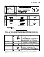
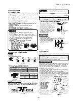
New tools for R-410A
Part
Code
A
B
C
Q'ty
Each
one
1
Each
one
Parts name
Refrigerant piping
Liquid side
:
∅
6.35 mm
Gas side
:
∅
9.52 mm
Pipe insulating material
(polyethylene foam, 6 mm thick)
Putty, PVC tapes
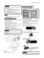
9-1-2. Optional Installation Parts
•
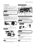
Secure the outdoor unit with the fixing bolts and nuts
if the unit is likely to be exposed to a strong wind.
•
Use
∅
8 mm or
∅
10 mm anchor bolts and nuts.
•
If it is necessary to drain the defrost water, attach
drain nipple to the bottom plate of the outdoor unit
before installing it.
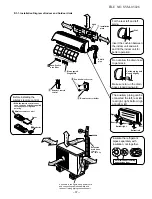
Fixing bolt arrangement of outdoor unit
Part name (Q'ty)
Mounting screw
∅
4 x 25
s
x 6
Flat head wood screw
∅
3.1 x 16
s
x 2
Drain nipple* x 1
Part
No.
1
2
3
Part name (Q'ty)
Installation plate x 1
Wireless remote control x 1
Battery x 2
Part name (Q'ty)
Remote control holder x 1
Sasa-Zeolite plus filter x 1
Bio-enzyme & Gingko filter x 1
This model is not equipped with an extension drain hose.
Option :
For the extension drain hose, use an optionally available
RB-821SW or commercially available one.
Name
Owner's manual
Installation manual
Others
The part marked with asterisk (*) is packaged with the outdoor unit.
Part
No.
4
5
6
Part
No.
7
8
9
Changes in the product and components
New tools for R-410A
Applicable to R-22 model
Changes
Gauge manifold
Charge hose
Electronic balance for
refrigerant charging
Torque wrench
(nominal diam. 1/2, 5/8)
Flare tool
(clutch type)
Gauge for projection adjustment
Vacuum pump adapter
Gas leakage detector
As pressure is high, it is impossible to measure by means of conventional gauge.
In order to prevent any other refrigerant from being charged, each port diameter
has been changed.
In order to increase pressure resisting strength, hose materials and port size
have been changed (to 1/2 UNF 20 threads per inch).
When purchasing a charge hose, be sure to confirm the port size.
As pressure is high and gasification speed is fast, it is difficult to read the
indicated value by means of charging cylinder, as air bubbles occur.
The size of opposite sides of flare nuts have been increased. Incidentally,
a common wrench is used for nominal diameters 1/4 and 3/8.
By increasing the clamp bar's receiving hole, strength of spring in the tool has
been improved.
Used when flare is made by using conventional flare tool.
Connected to conventional vacuum pump. It is necessary to use an adapter to
prevent vacuum pump oil from flowing back to the charge hose.
The charge hose connecting part has two ports-one for conventional refrigerant
(7/16 UNF 20 threads per inch) and one for R410A. If the vacuum pump oil
(mineral) mixes with R-410A a sludge may occur and damage the equipment.
Exclusive for HFC refrigerant.
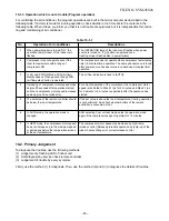
•
Incidentally, the “refrigerant cylinder” comes with the refrigerant designation (R-410A) and protector coating in the U.S's ARI specified rose color
(ARI color code: PMS 507).
•
Also, the “charge port and packing for refrigerant cylinder” require 1/2 UNF 20 threads per inch corresponding to the charge hose's port size.
B
50
D
A
C
265
240
Suction side
Drain hole
Diffuser
A
B
C
D
RAS-10UAV-E
275 500 60 97
9-1-3. Accessory and Installation Parts
Fig. 9-1-2
Содержание RAS-10NAV-A
Страница 17: ...FILE NO SVM 05026 16 4 2 Outdoor Unit ...
Страница 77: ...FILE NO SVM 02007 78 TOSHIBA CARRIER CORPORATION ...

