–
30
–
Item
2. Indoor fan
motor control
Operation flow and applicable data, etc.
<In cooling operation>
(This operation controls the fan speed at indoor unit side.)
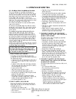
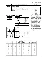
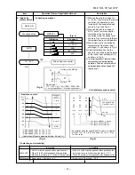
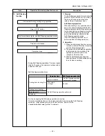
The indoor fan (cross flow fan) is operated by the phase-
control induction motor. The fan rotates in 5 stages in
MANUAL mode, and in 5 stages in AUTO mode, respec-
tively. (Table 1)
Description
* Symbols
UH
: Ultra High
H
: High
M+
:
M
: Medium
L+
: Low+
L
: Low
L-
: Low–
UL
: Ultra Low
SUL
: Super Ultra Low
* The values of fan speed and air flow
volume indicate on the table are
measured when the louver is inclined
downward. Fan speed and air flow
volume broadly vary with position
(Fig. 1)
(Fig. 2)
+2.5
Ta
[˚C]
+2.0
+1.5
+1.0
+0.5
Tsc
a
b
c
d
e
M+(WB)
*3
*4
*5
L(W6)
Air volume AUTO
L
L+
M
M+
H
W6
(L + M) / 2
W9
(M + H) / 2
WC
Indication
Fan speed
Fan speed setup
COOL ON
AUTO
MANUAL
*3 : Fan speed = (M + –L) x 3/4 + L
*4 : Fan speed = (M + –L) x 2/4 + L
*5 : Fan speed = (M + –L) x 1/4 + L
(Linear approximation
from M+ and L)
FILE NO. SVM-12057
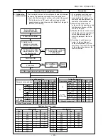
(Table 1) Indoor fan air flow rate
Quiet L
−
of louver.
1) When setting the fan speed to L,
L+, M, M+,H or Quiet on the
remote controller, the operation is
performed with the constant
speed shown in Fig. 1.
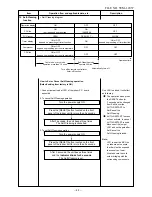
2) When setting the fan speed to
AUTO on the remote controller,
revolution of the fan motor is
controlled to the fan speed level
shown in Fig. 2 and Table 1
according to the setup tempera-
ture, room temperature, and heat
exchanger temperature.
WF
UH
WE
H
WD
UH
M+
UH
WC
H
H
WB
M+
M+
M+
WA
M
W9
M L+
W8
L
W7
L+
L-
L+
W6 L L
W5
L-
UL
L-
W4
UL
UL
W3
SUL
SUL
W2
SUL
W1
253
222
129
129
359
347
291
291
650
500
500
571
571
546
515
465
440
415
850
760
760
700
1040
1000
960
870
1210
1210
1170
1120
Air flow rate
(m3/h)
(rpm)
Fan speed
HEAT
COOL
DRY
Fan speed
level
RAS-10N3KVR-E
266
234
141
129
359
353
297
297
670
520
500
620
620
590
570
490
465
434
860
770
770
720
1080
1050
990
870
1300
1300
1250
1200
Air flow rate
(m3/h)
(rpm)
Fan speed
RAS-1
3
N3KVR-E


