


– 65 –
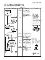
Operation
Measure
Item by symptoms
Check item
Conceivable principle
cause
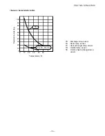
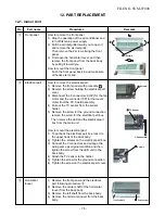
Parts
(D01 ~ D04,
C03, T101
and IC12 are
defective.
•
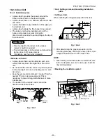
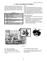
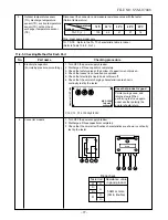
Be sure to disconnect the motor connector CN10 after shut off the power supply, or it will be a cause of
damage of the motor.
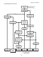
(1) Power is not turned on (Does not operate entirely)
3
FILE NO. SVM-0
7008
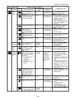
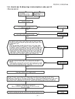
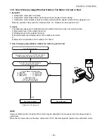
11-5. Judgement of Trouble by Every Symptom
11-5-1. Indoor unit (Including remote controller)
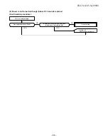
Turn off power
supply once, and 5
second later, turn it
on again.
Is OPERATION
lamp blinking?
NO
YES
NO
NO
YES
YES
Is it possible to
turn on power
supply by
pressing
[ ] button
on remote
control?
Does
transmission
mark on
remote control
flash normally,
and is its signal
transmitted
properly?
Remote control is
defective.
Refer to (5)
Remote Control.
"
Is fuse (F01)
of indoor control
board blown?
Is voltage
(DC 12V or 5V)
indicated on
rear of indoor
control board
normal?
Microcomputer
is defective.
Replace main
P.C. board.
Refer to
<Primary check>
or this problem
is one step short
of power P.C.
Is the
voltage
across C03
mesured
YES
YES
NO
NO
NO
NO
YES
Does
fan motor
connector
between 1
and
short-circuit?
Unit operates
normally.
board block.
Are DC 5V,
DC 12V
supplied
to main
P.C. board?
Turn off breaker
once and turn it
on again after
removing motor.
Regulator IC
(
IC12) or T101
are defective
Replace motor
.
NO
NO
YES
YES
YES
Are DC 5V,
or DC 12V
supplied
to main
P.C. board?
"Troubleshooting for
DC 310V~340V?
Содержание RAS-10N3ACV Series
Страница 16: ...FILE NO SVM 07008 15 4 2 Outdoor Unit C L C L ...
Страница 17: ... 16 FILE NO SVM 07008 5 WIRING DIAGRAM 5 1 Indoor Unit ...
Страница 18: ...FILE NO SVM 07008 17 5 2 Outdoor Unit ...
Страница 83: ...FILE NO SVM 07008 82 P C board layout Solder side ...
Страница 94: ...FILE NO SVM 03008 87 TOSHIBA CARRIER CORPORATION ...


