– 38 –
FILE NO. SVM-02005(1)
D
C
A
B
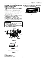
Valve stem cap connection
Flare nut connections
(Outdoor unit)
Electric parts cover
Flare nut connections
(indoor unit)
Valve stem cap
connection
Service cap
connection
8-7. Others
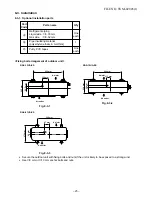
8-7-1. Gas leak test
For RAS-07UA-ES
Fig. 8-7-1
For RAS-13UA-ES, RAS-10UA-ES
•
Check the flare nut connections, valve stem cap
connections and service port cap connections for
gas leak with a leak detector or soap water.
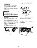
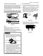
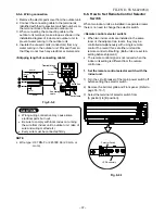
8-7-2. Test operation
To switch the TEST RUN (COOL) mode, press
TEMPORARY button for 10 sec.
(The beeper will make a short beep.)
Fig. 8-7-3
Valve stem cap
connection
Service cap
connection
Valve cover
Fig. 8-7-2
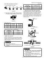
2. Set the remote control selector switch with the
remote control
[B] is indicated on the liquid crystal display when
setting remote control selector switch to B. [A] is not
indicated on the display even if the selector switch
is set to A.
1) Load the remote control with the batteries.
2) Press the [CHECK] button using something with
sharp point. (The preset temperature on the remote
control changes to [00].)
3) Press the [MODE] button while pressing the
[CHECK] button, [B] is indicted at the right of the
present temperature display.
•
To reset the switch to the [A] setting, press the
[MODE] button again while pressing the [CHECK]
button.
Fig. 8-6-2
3. Confirm that the indoor unit can operate with
the new setting.
[MODE] button
[CHECK] button
PRESET
FAN
MODE
Hi-POWER
ON
OFF
SET
CLR
ECO
AUTO
TIMER
CLOCK CHECK
RESET
FILTER
FIX
SWING
MEMO
START/STOP
A
B
A
B
TEMPORARY button
TEMPORARY button


