background image

USER MANUAL

Safety Precautions

Unit Specifications

Operating Instructions

Installation Instructions

Remote Control Operating 
Instructions

Troubleshooting Tips

Care and Cleaning

RAC-WK0511CMU

RAC-WK0611CRU

RAC-WK0811ESCWU

RAC-WK1011ESCWU

RAC-WK1211ESCWU

RAC-WK1511ESCRU

RAC-WK1821ESCRU

Warning notices: Before using this product,
please read this manual carefully and keep
it for future reference.
The design and specifications are subject to
change without prior notice for product
improvement. Consult with your dealer or
manufacturer for details.

version A - 09 - 2017

www.toshibaappliances.com

Safety P

Un

it S

pe

O

Oper

at

in

stallat

Ins

Tr

o

Ca

Op

Ins

Содержание RAC-WK0511CMU

Страница 1: ... RAC WK1011ESCWU RAC WK1211ESCWU RAC WK1511ESCRU RAC WK1821ESCRU Warning notices Before using this product please read this manual carefully and keep it for future reference The design and specifications are subject to change without prior notice for product improvement Consult with your dealer or manufacturer for details version A 09 2017 www toshibaappliances com Safety P Unit Spe O Operatin sta...

Страница 2: ...r safety Contact the authorized service technician for repair or maintenance of this unit Contact the installer for installation of this unit The air conditioner is not intented for use by young children or infirm persons without supervision Young children should be supervised to ensure that they do not play with the air conditioner If the power cord needs to be replaced please contact our consume...

Страница 3: ...ate with wet hands or in very humid enviroments It may cause electric shock Do not allow water to touch into electric parts It may cause failure or electric shock Do not use the socket if it is loose or damaged It may cause fire and electric shock Do not use or keep the power cord close to heating appliances It may cause fire and electric shock Do not place the power cord close to heating applianc...

Страница 4: ...he insulation It may cause an electric shock Do not put a pet or house plant where it will be exposed to direct air flow This could injure the pet or plant Hold the plug by the head of the power plug when taking it out It may cause electric shock and damage Ensure that the installation is properly secured under risk of the product falling Do not place heavy object on the power cord and ensure that...

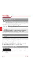
Страница 5: ...alling this unit The complete electrical rating of your new room air conditioner is stated on the serial plate Refer to the rating when checking the electrical requirements Be sure the air conditioner is properly grounded To minimize shock and fire hazards proper grounding is important The power cord is equipped with a three prong grounding plug for protection against shock hazards Your air condit...

Страница 6: ... button engages 4 The power supply cord is now supplying electricity to the unit On some products this it also indicated by a light on the plug head Operation of Current Device Do not use this device to turn the unit on or off Always make sure the RESET button is pushed in for correct operation The power supply must be replaced if it fails reset when either the TEST button is pushed or it can not ...

Страница 7: ... 59 5 58 5 57 Plug type 5 15P 5 15P 5 15P 5 15P Control type Mechanical Control Remote Control Remote Control Remote Control Operating temperature Indoor cooling heating C 17 32 17 32 17 32 17 32 F 62 90 62 90 62 90 62 90 Outdoor cooling heating C 18 43 18 43 18 43 18 43 F 64 109 64 109 64 109 64 109 Application area Cooling EPA sq ft 100 150 150 250 300 350 400 450 Dimension W D H mm 406x392x306 ...

Страница 8: ... 353 308 250 360 320 280 Indoor noise level Hi Med Lo dB A 60 5 59 3 57 7 56 4 53 7 52 5 60 57 54 Plug type 5 15P 5 15P 5 15P Control type Remote Control Remote Control Remote Control Operating temperature Indoor cooling heating C 17 32 17 32 17 32 F 62 90 62 90 62 90 Outdoor cooling heating C 18 43 18 43 18 43 F 64 109 64 109 64 109 Application area Cooling EPA sq ft 450 550 550 700 700 1000 Dime...

Страница 9: ... may have a high pitched sound during cooling cycle Vibration Unit may vibrate and make noise because of poor wall or window construction or incorrect installation Pinging or Switching Droplets of water hitting condenser during normal operation may cause pinging or switching Gurgle Hiss Gurgling or hissing noise may be heard due to refrigerant flowing through evaporator during normal operation Sou...

Страница 10: ...erating the air conditioner follow these steps 1 Set the thermostat to the highest number coldest or cooler setting 2 Set the selector control to the highest COOL setting 3 Adjust the louver for comfortable air flow see Air Directional Louvers 4 Once the room feels cooled adjust the thermostat to the setting you find most comfortable 5 Make sure that the air flow inside and outside are not obstruc...

Страница 11: ...mperature when the unit is being operated in the COOL MODE To set the desired room temperature rotate the thermostat switch to the desired setting After the set temperature is achieved the thermostat will automatically start and stop the compressor in order to maintain the desired set temperature Rotate the thermostat selector clockwise for higher cool settings Higher cool settings will provide lo...

Страница 12: ...ctions mode and the unit will continue to operate as originally programmed The Sleep mode program can be cancelled at any time during operation by pressing the Sleep button again CHECK FILTER FEATURE Press Check filter button to initiate this feature This feature is a reminder to clean the Air Filter for more efficient operation The LED light will illuminate after 250 hours of operation To reset a...

Страница 13: ...ndicates the Auto Start program is initiated When the time of TIMER ON is displayed press the Timer button again the TIMER OFF indicator light illuminates It indicates the Auto Stop program is initiated Press or hold the UP or DOWN button to change the Auto time by 0 5 hour increments up to 10 hours then at 1 hour increments up to 24 hours The control will count down the time remaining until start...

Страница 14: ...it or degrees Celsius To convert from one to the other press and hold the left or right Temp Timer buttons at the same time for 3 seconds The louvers will allow you to direct the air flow Up or Down on some models and Left or Right throughout the room as needed Pivot horizontal louvers until the desired Up Down direction is obtained Move the Levers from side to side until the desired Left Right di...

Страница 15: ... procedures as described in these instructions when installing this air conditioner CAUTION Do not under any circumstances cut or remove the third ground prong from the power cord Do not change the plug on the power cord of the air conditioner Aluminum house wiring may present special problems consult a qualified electrician When handling unit be careful to avoid cuts from sharp metal edges and al...

Страница 16: ...nside a building or garage Mounting Hardware 3 4 or 1 2 Screws 7 Lock Frame 2 Sash Lock 1 Window sash seal foam 1 Weather stripping 10 3 4 1 12 5 A Remove the air conditioner from the carton and place on a flat surface B Remove top rail and R1 hardware R1 hardware only for Energy star models from the packaging material as shown in Fig A 3 8 Screws 4 Top Rail 1 R1 Hardware 2 Top Rail Hardware Packa...

Страница 17: ... MUST be securely fastened RAC WK05 Models RAC WK06 08 10 12 15 18Models 3 Install the Accordion Panels Air Conditioner NOTE NOTE The top rail hardware and the Fig A Fig B and Fig C are not applicable to the units more than 10000 Btu h Before installing unit the top rail must be assembled on the unit For 10000 Btu h models only Top rail and Sliding Panels at each side are offset to provide the pro...

Страница 18: ... Bottom Rail Top left Top right Fig 4 D Slide the panel all the way in and repeat on the other side 4 Secure the Accordion Panels NOTE Check that air conditioner is tilted back about H Fig 5 tilted about 3 to 4 downward to the outside After propor installation condensate should not drain from the overflow drain hole during normal use correct the slope otherside A Keep a firm grip on the air condit...

Страница 19: ...gh frame holes into window sash Fig 8 C To secure lower sash in place attach right angle sash lock with 3 4 19mm or 1 2 12 7mm screw as shown Fig 9 D Cut Window sash seal foam and insert it in the space between the upper and lower sashes Fig 10 B Extend the side panels out against the window frame Fig 6 5 Install Support Bracket NOTE To prevent window sill from splitting drill 1 8 3mm pilot holes ...

Страница 20: ...ow measure the inner width of the side curtain as shown Fig 11 Measure the inner width of the side curtain Fig 11 Fig 11 Fig 12 or Fig 13 Step 2 Remark a line on the provide R1 insulation panel according to a length 1 8 3mm less than the measured width in step 1 then cut the R1 insulation panel along the line Fig 12 Step 3 Slide the R1 insulation panel into the side curtain the side with pattern s...

Страница 21: ...truction Fig 15 Add wood as shown in Fig 15 or remove storm window before air conditioner is installed If storm window frame must remain be sure the drain holes or slots are not caulked or painted shut Accumulated rain water or condensation must be allowed to drain out Turn AC off and disconnect power cord Remove sash seal from between windows and unscrew safety lock Remove screws installed throug...

Страница 22: ...hat two people install this product Proper installation is the responsibility of the installer Product failure due to improper installation is not covered under the Warranty You MUST use all supplied parts and use proper installation procedures as described in these instructions when installing this air conditioner CAUTION Do not under any circumstances cut or remove the third ground prong from th...

Страница 23: ...e unit serial nameplate Power cord is 48 in long Be sure you have an outlet near 6 Carefully unpack air conditioner Remove all packing material Protect floor or carpet from damage Two people should be used to move and install unit SASH 19 MIN StormWindow Frame or Other Obstruction Board Thickness as Required Along Entire Stool Fasten WithTwo Nails Or Screws 1 2 MIN 1 2 MIN Fig E 7 16 in Locking sc...

Страница 24: ...h metal cabinet side to release plastic tabs on each side of front panel see Fig 3 5 Gently lift front panel off unit see Fig 3A 6 Disconnect the connector plug of the display panel from the unit and place front panel to one side see Fig 4 7 Remove shipping screws from top of unit and also on the side by the base if installed see Fig 5 8 Hold the cabinet while pulling on the base pan handle and ca...

Страница 25: ...in Fig 8 10 screws Fig 10 TOP VIEW Air Conditioner Cabinet Plastic Frame Locking Screw Hole Window Filler Panel I Section Fig 8 5 16 long hex head Plastic Frame Side Retainer Window Filler Panel Fig 9 3 Assemble Window Filler Panels 1 Place cabinet on floor a bench or a table 2 Slide I section of window filler panel into side retainer on the side of the cabinet see Fig 9 Fig 10 Do both sides 3 Ins...

Страница 26: ...ft or right as needed to line up center of cabinet on center line marked on stool 4 Fasten cabinet to window stool with 2 screws into holes You may wish to pre drill pilot holes 5 Add bottom rail seal over screws to window stool Fig 13 Fig 11 Stool Stool Angle Fig 12 Bottom Rail Seal 3 4 or 1 2 Long Hex head Screw Fig 13 5 Install Support Bracket 1 Hold each support bracket flush against outside o...

Страница 27: ...quired For Each Support Bracket 1 2 Long Screws and Locknuts 2 Assemble sill angle bracket to support brackets at the marked position Fig 15B Hand tighten but allow for any changes later 3 Install support brackets with sill angle brackets attached to correct hole in bottom of cabinet as shown in Fig 16 4 Tighten all 6 bolts securely 6 Extend Window Filler Panels 1 Carefully raise window to expose ...

Страница 28: ... Channel Window Channel A B C Wheather seals A 3 4 or 1 2 long hex head screw A Fig 18B 7 AttachWindow Filler Panels toWindow Frame 1 Extend the window filler panels out against the window frame 2 Use a 1 8 in drill bit to drill a starter hole through the hole in the top leg of each window filler panel and into the window sash Fig 18A and Fig 18B Connect with one 3 4 or 1 2 long hex head screw Win...

Страница 29: ...r to minimize air leaks and ensure optimal insulation it is necessary to install the included R1 hardware to the side curtain Follow the instructions below Step 1 After the unit is installed to the window measure the inner width of the side curtain as shown Fig 20 Step 2 Remark a line on the provide R1 insulation panel according to a length 1 8 3 mm less than the measured width in step 1 then cut ...

Страница 30: ...T Side louvers must never be blocked Fig 23 NOTE Consult local building codes prior to installation or a qualified carpenter NOTE All parts needed for Thru The Wall Installtion are provided except a wood frame shims and 10 wood screws 10 1 in long minimum Select a wall surface that 1 Does not support major structural loads such as the frame construction at ends of windows and under truss bearing p...

Страница 31: ...g on your model See Fig 24 and Fig 25 WIDTH X inside model width plus twice the thickness of framing material used HEIGHT Y inside model height plus twice the thickness of framing material used Inside Frame Height 18 7 8 in 47 9 cm or 18 in 45 7 cm Inside Frame Width 26 3 4 in 67 9 cm or 23 7 8 in 60 6 cm 4 Build a wooden frame with the INSIDE dimensions of your model listed above Measure twice re...

Страница 32: ...er clearance on either side of cabinet 3 Install a lintel to support masonry wall above cabinet Existing holes in cabinet can be used and or additional holes can be drilled to fasten cabinet at various positions Be sure that side louver clearance is in accordance with Step 1 above 4 Install exterior cabinet support brackets as shown in Step 2 of Thru the wall installation Caulk or flash if needed ...

Страница 33: ...zard The cabinet and front may be dusted with an oil free cloth or washed with a cloth dampened in a solution of warm water and mild liquid dishwashing detergent Rinse thoroughly and wipe dry Never use harsh cleaners wax or polish on the cabinet front Be sure to wring excess water from the cloth before wiping around the controls Excess water in or around the controls may cause damage to the air co...

Страница 34: ...orming on cooling coil behind decorative front Air filter may be dirty Clean filter Refer to Care and Cleaning section To defrost set to FAN ONLY mode Temperature is set too High set temperature to a lower setting Air directional louvers positioned improperly Position louvers for better air distribution Front of units is blocked by drapes blinds furniture etc restricts air distribution Clear block...

Страница 35: ...IONS Step 1 Insert a coin vertically in the groove on the battery cover clockwise rotation of 45 degrees make sure that the groove is aligned with the unlock sign as shown below and remove the battery cover Step 3 Install the battery cover make sure the battery cover groove is aligned with the unlock sign Insert a coin vertically in the groove and press it gently then counter clockwise rotation of...

Страница 36: ...ed on typical model and might be slightly different from the actual one you purchased the actual shape shall prevail All the functions described are accomplished by the unit if the unit has no this feature there is no corresponding operation happened when press the relative button on the remote controller When there are wide differences between Remote Controller Illustration and USERS MANUAL on fu...

Страница 37: ...AT or AUTO mode only and maintain the most comfortable temperature for you and save enrgy For the detail see sleep operation in USER S MANUAL Press this button to activate the Energy saving mode Press it again to stop the funtion on some models Push this button to decrease the indoor temperature setting Push this button to activate the Auto Start or Auto Stop program Push this button the system wi...

Страница 38: ...button to set the desired temperature 4 Press the FAN button to select the fan speed 1 2 3 3 1 2 3 3 4 How to Use the Buttons NOTES 1 In the Auto mode the air conditioner can logically choose the mode of Cooling Fan Heating and by sensing the difference between the actual ambient room temperature and the set temperature on the remote controller 2 In the Auto mode you can not switch the fan speed I...

Страница 39: ...n the TIMER ON indicator displayed on the LED window of the air conditioner it indicates the Auto Start setting program is initiated When the TIMER OFF indicator displayed on the LED window of the air conditioner it indicates the Auto Stop setting program is initiated 2 Press or hold the Up or Down to change the Auto time The control will count down the time remaining until start stop 3 The select...

Страница 40: ...n the LED display of the unit 4 Use the UP DOWN button to display 10 on the LED display of the unit 5 Wait for 5 seconds until the previous display revert back to the LED window AUTO START AUTO STOP Off Start Stop operation This feature is useful when you want to start the air conditioner before you wake up and stop it after you leave the house Example To start the air conditioner 5 hours after se...

Страница 41: ...rference and 2 this device must accept any interference received including interference that may cause undesired operation This equipment has been tested and found to comply with the limits for a Class B digital device pursuant to part 15 of the FCC Rules These limits are designed to provide reasonable protection against harmful interference in a residential installation This equipment generates u...

Страница 42: ...ters the body it can cause severe internal burns and can lead to death in as little as 2 hours Always completely secure the battery compartment If the battery compartment does not close securely stop using the product remove the batteries and keep it away from children If you think batteries might have been swallowed or placed inside any part of the body seek immediate medical attention ...

Отзывы: