DISASSEMBLY INSTRUCTIONS
B1-1
1. REMOVAL OF MECHANICAL PARTS
AND P.C. BOARDS
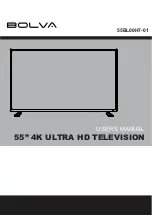
1-1: BACK CABINET (Refer to Fig. 1-1)
1.
2.
3.
Remove the 7 screws
1
.
Remove the AC cord from the AC cord hook
2
.
Remove the Back Cabinet in the direction of arrow.
1-2: CRT PCB (Refer to Fig. 1-2)
CAUTION: BEFORE REMOVING THE ANODE CAP,
DISCHARGE ELECTRICITY BECAUSE IT
CONTAINS HIGH VOLTAGE.
BEFORE ATTEMPTING TO REMOVE OR
REPAIR ANY PCB, UNPLUG THE POWER
CORD FROM THE AC SOURCE.
1.
2.
3.
Remove the Anode Cap.
(Refer to REMOVAL OF ANODE CAP)
Disconnect the following connector: (CP801).
Remove the CRT PCB in the direction of arrow.
Fig. 1-1
Front Cabinet
Back Cabinet
CRT PCB
Fig. 1-2
Front Cabinet
1-3: TV/VCR BLOCK (Refer to Fig. 1-3)
Fig. 1-3
1.
2.
3.
4.
Remove the 2 screws
1
.
Disconnect the following connectors:
(CP352, CP354, CP401 and CP502).
Unlock the support
2
.
Remove the TV/VCR Block in the direction of arrow.
UP TO
RELEASE
TV/VCR Block
Front Cabinet
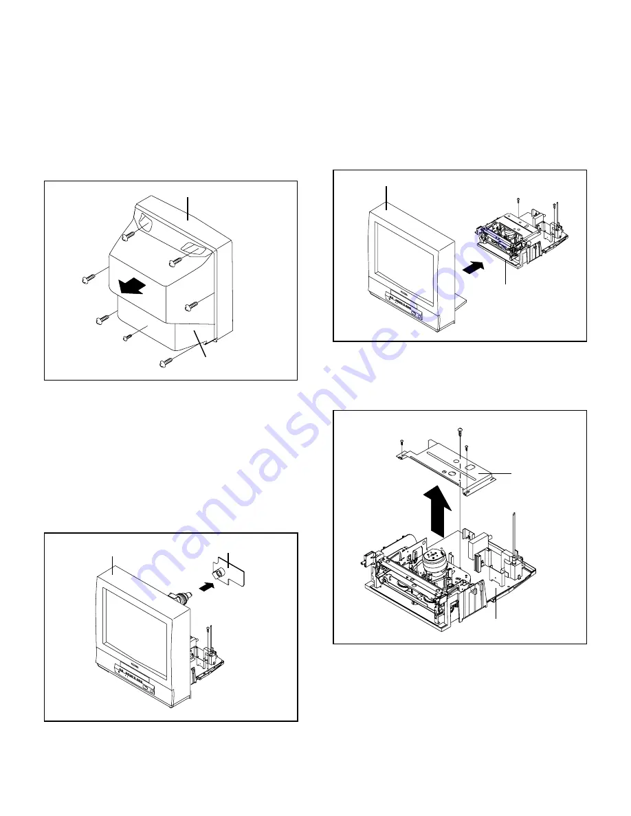
1-4: DECK SHIELD PLATE (Refer to Fig. 1-4)
1.
2.
3.
Remove the 2 screws
1
.
Remove the screw
2
.
Remove the Deck Shield Plate in direction of arrow.
Fig. 1-4
TV/VCR Block
Deck Shield Plate
1
1
1
1
1
1
1
2
2
1
1
2
1
1
Содержание MV20P2C
Страница 1: ...SERVICE MANUAL COLOR TELEVISION VIDEO CASSETTE RECORDER MV20P2C FILE NO 140 200418 ...
Страница 57: ...MECHANICAL EXPLODED VIEW PACKING DIAGRAM I1 3 119 123 124 BL001 TM101 120 121 118 117 119 ...
Страница 66: ...TOSHIBA CORPORATION 1 1 SHIBAURA 1 CHOME MINATO KU TOKYO 105 8001 JAPAN ...