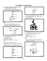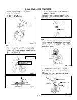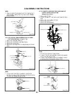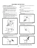
DISASSEMBLY INSTRUCTIONS
B2-6
1
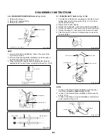
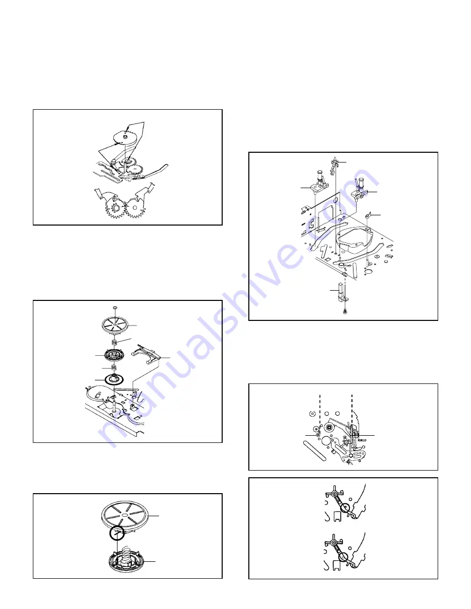
Clutch Ass’y
Ring Spring
Clutch Lever
Coupling Gear
Coupling Spring
Clutch Gear
NOTE
1. When you install the Loading Arm S Unit, Loading Arm T
Unit and Main Loading Gear, align each marker. (Refer
to Fig. 2-16-B)
Fig. 2-16-B
Marker
Main Loading Gear
Loading Arm T Unit
Loading Arm S Unit
Marker
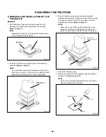
2-17: CLUTCH ASS’Y/RING SPRING/CLUTCH LEVER/
CLUTCH GEAR (Refer to Fig. 2-17-A)
1.
2.
3.
4.
Remove the Polyslider Washer
1
.
Remove the Clutch Ass’y and Ring Spring.
Remove the Clutch Lever.
Remove the Coupling Gear, Coupling Spring and Clutch
Gear.
Fig. 2-17-A
NOTE
1. In case of the Clutch Ass’y installation, install it with
inserting the spring of the Clutch Ass’y into the dent of the
Coupling Gear. (Refer to Fig. 2-17-B)
Fig. 2-17-B
Clutch Ass’y
Coupling Gear
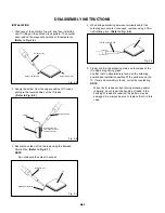
2-18:
Remove the P4 Cap.
Unlock the support
1
and remove the Cassette Guide
Post.
Remove the Inclined Base S/T Unit.
Remove the screw
2
.
Remove the LED Reflector.
1.
2.
3.
4.
5.
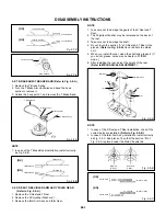
Fig. 2-18-A
CASSETTE GUIDE POST/INCLINED BASE S/T
UNIT/P4 CAP/LED REFLECTOR
(Refer to Fig. 2-18-A)
P4 Cap
Cassette Guide Post
1
Inclined Base T Unit
Inclined Base S Unit
2
LED Reflector
NOTE
1.
2.
3.
Do not touch the roller of Guide Roller.
In case of the P4 Cap installation, install it with parallel
for “A” and “B” of Fig. 2-18-B.
In case of the Cassette Guide Post installation, install
correctly as the circled section of Fig. 2-18-C.
Fig. 2-18-B
“A”
“B”
P4 Cap
Cassette Opener
[OK]
Cassette Guide Post
[NG]
Cassette Guide Post
Fig. 2-18-C
Содержание MV13P2C
Страница 1: ...SERVICE MANUAL COLOR TELEVISION VIDEO CASSETTE RECORDER MV13P2C FILE NO 140 200416 ...
Страница 56: ...118 119 116 MECHANICAL EXPLODED VIEW PACKING DIAGRAM I1 3 121 124 BL001 TM101 117 117 117 117 118 118 118 115 ...
Страница 65: ...TOSHIBA CORPORATION 1 1 SHIBAURA 1 CHOME MINATO KU TOKYO 105 8001 JAPAN ...

