


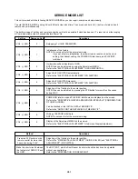
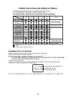

B1-1
Front Cabinet
CRT PCB
DISASSEMBLY INSTRUCTIONS
1. REMOVAL OF MECHANICAL PARTS
AND P.C. BOARDS
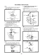
1-1: BACK CABINET (Refer to Fig. 1-1)
1.
2.
3.
4.
5.
6.
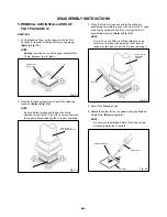
1-3: TV/VCR BLOCK (Refer to Fig. 1-3)
Fig. 1-3
Remove the 4 screws
1
.
Remove the screw
2
.
Remove the 2 screws
3
.
Remove the 2 screws
4
which are used for holding
the Back Cabinet.
Remove the AC cord from the AC cord hook
5
.
Remove the Back Cabinet in the direction of arrow.
Fig. 1-1
Front Cabinet
Back Cabinet
1
1
1
2
1
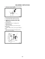
1-2: CRT PCB (Refer to Fig. 1-2)
CAUTION: BEFORE REMOVING THE ANODE CAP,
DISCHARGE ELECTRICITY BECAUSE IT
CONTAINS HIGH VOLTAGE.
BEFORE ATTEMPTING TO REMOVE OR
REPAIR ANY PCB, UNPLUG THE POWER
CORD FROM THE AC SOURCE.
1.
2.
3.
Fig. 1-2
1.
2.
3.
4.
Remove the 2 screws
1
.
Disconnect the following connectors:
(CP353, CP401 and CP403).
Unlock the support
2
.
Remove the TV/VCR Block in the direction of arrow.
Remove the Anode Cap.
(Refer to REMOVAL OF ANODE CAP)
Disconnect the following connectors:
(CP801 and CP850).
Remove the CRT PCB in the direction of arrow.
1
1
2
UP TO
RELEASE
TV/VCR Block
Front Cabinet
3
3
4
4
5
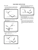
1-4: MAIN PCB (Refer to Fig. 1-4)
1.
2.
3.
4.
5.
6.
7.
Remove the screw
1
.
Remove the Main PCB Holder.
Remove the 2 screws
2
.
Remove the screw
3
.
Remove the 2 screws
4
.
Disconnect the following connectors:
(CP502 and CP820).
Remove the Main PCB in the direction of arrow.
Fig. 1-4
Main PCB Holder
1
VCR Block
Main PCB
4
4
2
2
3
Содержание MV 9DM2
Страница 1: ...SERVICE MANUAL COLOR TELEVISION VIDEO CASSETTE RECORDER FILE NO 140 200203 MV9DM2 ...
Страница 51: ...SERVICE MANUAL COLOR TELEVISION VIDEO CASSETTE RECORDER FILE NO 140 200203 MV9DM2 ...
Страница 68: ...TOSHIBA VIDEO PRODUCTS PTE LTD 438B ALEXANDRA ROAD BLOCK B 06 01 ALEXANDRA TECHNOPARK SINGAPORE 119968 ...


