


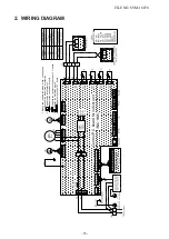


2. WIRING DIAGRAM
DC12V
DC 7V
DC15V
DC20V
A
B
1
3
5
1
2
3
4
5
6
7
8
9
10
2
1
3
5
3
1
2
4
5
3
1
2
4
6
2
1
2
1
2
1
1
2
t°
3
1
2
2
1
5
3
1
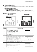
2
4
7
1
5
4
3
6
MS
1
L
5
4
3
2
5
3
1
2
4
6
5
M
N
1
3
4
5
6
2
8
7
9
A
B
t°
t°
U2
U1
6
1
3
4
5
2
2
1
t°
1
3
M
6
U2
U1
Control P.C board for indoor unit
short dashed line indicate the accessories.
indicates the control P.C. board.
indicates the terminal block.
indicates the connection terminal.
indicates the connector on the control P.C. board.
1.Broken line indicate the wiring at site. Long dashed
indicates the protection ground.
4.
3.
2.
11
10
11
5
3
1
2
4
5
FILE NO. SVM-18070
- 15 -


