– 2 –
CONTENTS
PRECAUTIONS FOR SAFETY ................................................................................ 6
1. SPECIFICATIONS .................................................................................................. 13
2. AIR DUCTING WORK............................................................................................. 1
5
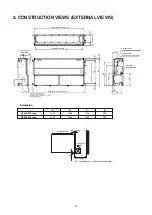
3. CONSTRUCTION VIEWS (EXTERNAL VIEWS) ....................................................
17
4. WIRING DIAGRAMS ...............................................................................................
20
5. PARTS RATING.................................................................................................
.
..... 2
1
6. REFRIGERANT CYCLE DIAGRAM .....................................................................
.
.. 2
2
7. CONTROL OUTLINE.............................................................................................
.
. 2
3
8. APPLIED CONTROL AND FUNCTIONS
(INCLUDING CIRCUIT CONFIGURATION) .........................................................
.
.
2
9
8-1. Indoor controller block diagram ........................................................................................
2
9
8-1-1. In Case of Connection of Wired (Simple) Remote Controller
............................. 2
9
8-1-2. In Case of Connection of Wireless Remote Controller
.......................................
30
8-1-3. Connection of Both Wired (Simple) Remote Controller and Wireless Remote
Controller .................................................
........................................................
....... 3
1
8-2. Indoor Print Circuit Board MCC-1631
........................................................
......
.............
.... 3
2
8-3. Optional connector specifications of indoor P.C. board
................................................
3
3
8-4. Test operation of indoor unit .............................................................................................
3
4
8-5. Method to set indoor unit function DN code ....................................................................
3
5
8-6. Applied control of indoor unit ...........................................................................................
3
8
9. TROUBLESHOOTING ......................................................................................
.
......
5
4
9-1. Overview ..............................................................................................................................
5
4
9-2. Troubleshooting method ...................................................................................................
5
5
9-3. Troubleshooting based on information displayed on remote controller ....................... 6
1
9-4. Check codes displayed on remote controller and SMMS outdoor unit
(7-segment display on I/F board) and locations to be checked ....................................
6
6
9-5. Sensor characteristics .......................................................................................................
8
5
10. P.C. BOARD EXCHANGE PROCEDURES..........................................................
8
6
10-1. Replacement of indoor P.C. boards.................................................................................
8
6
11. DETACHMENTS .............................................................................................
..
....
9
2
12. EXPLODED VIEWS AND PARTS LIST .........................................................
..
....
9
8
Содержание MMD-AP0186HP-E
Страница 20: ... 20 4 WIRING DIAGRAMS ...

