–
88
–
Procedure 2: replacing P.C. board
1
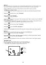
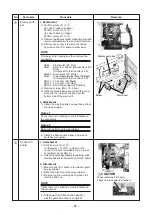
Replace the faulty P.C. board with a service P.C. board.
Be sure to replicate the old jumper setting (removal), switch setting (SW501), and connector short-circuit setting (e.g.
CN34) on the service P.C. board. (See the diagram at below.)
2
It is necessary to establish a one-to-one correspondence between the indoor unit being
serviced and the remote controller.
Turn on the indoor unit using one of the methods described below according to the system configuration.
(1) Single (stand-alone) operation
Turn on the indoor unit and proceed to
Procedure 3
.
(2) Group operation
A)If it is possible to selectively turn on the indoor unit being serviced
Turn on the indoor unit being serviced and proceed to
Procedure 3
.
B)If it is not possible to selectively turn on the indoor unit being serviced
(Case 1)
a) Temporarily disconnect the group control wiring from terminals A and B of the indoor unit being serviced.
b) Connect the remote controller wiring to the terminals, turn on the indoor unit, and proceed to
Procedure 3
.
* If this method cannot be used, proceed to the alternative method described below
(Case 2)
.
C)If it is not possible to selectively turn on the indoor unit being serviced (Case 2)
a) Remove the CN41 connectors of all other indoor units in the same group.
b) Turn on the indoor unit and proceed to
Procedure 3
.
* Be sure to restore the temporarily removed group control wiring and CN41 connectors to their initial states
after Procedure 3 has been completed.
CAUTION
Don’t remove the materials.
No materials. The power I.C. (IC101) may break.
A B
A B
A B
Indoorunit
P.C. board
Indoorunit
P.C. board
Indoorunit (one being serviced)
Service P.C. board
Remote
controller
Group contrpl wiring
A B
A B
Indoorunit
P.C. board
A B
Indoorunit
P.C. board
Indoorunit (one being serviced)
Service P.C. board
Remote
controller
Group contrpl wiring
Case 1
Case 2
Remove group control wiring
from terminals A and B of
indoor unit being serviced,
and connect remote controller
wiring.
Remove CN41
connectors of all
other indoor units
in same group.
CN
41
< The front of the P. C. Board>
< The Back of the P. C. Board>
J01
CN73
(RED)
T01
IC503
SW501
IC101
C08
C09
Materials
Perform the same setting of the jumper wire(J01) setting(cut),
switch(SW501) as the setting of the P. C. board before replacement
1
2

