background image

– 22 –

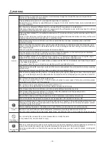
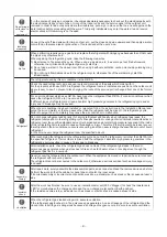
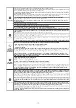
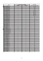
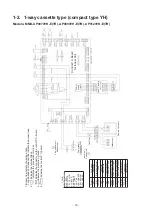
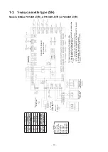
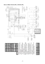
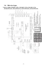
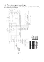
1-7. Ceiling type

Models: MMC-AP0154H-E(TR), AP0184H-E(TR), AP0244H-E(TR), AP0274H-E(TR), 
AP0364H-E(TR), AP0484H-E(TR)

Remote Co

ntr

o

ller

Ou

tdo

o

r unit

Control P.C. 

Board for 

Indoor U

n

it

Po

we

sup

p

ly 

circuit

A

dapt

e

r for

 Wirel

e

ss 

Remo

te Contro

ller

1.

Broken li

ne indicate the wiring 

at site.

Long dashed short 

dashed

 l

ine indicate the 

accessories.

2.

 indicates the terminal block.

 ind

icates th

e co

nne

ctio

n te

rmin

a

l.

 indicates the connector on the control

 P.C. 

bo

ard.

3.

 indicates the protecti

on ground.

4.

 indicates the co

ntrol P.C. board.

5.

When install

ing 

the drai

n pump connect 

the froat 

switch connector

 to CN34 

connector.

RED

 : 

RED

WHI

 : WHITE

YE

L

 :

 Y

E

L

L

OW

BLU : 

BLUE

B

L

K : BL

ACK

GRY

 :

 G

R

A

Y

P

N

K :

 PINK

ORN : ORA

N

G

E

BRW : BRO

W

N

GRN : GRE

E

N

COL

O

IDENTIFICATION

Symbol

P

a

rt

s

 Name

CN**

C

o

n

nector

F301,302

F

use

FM

Fan

 Motor

LM

Lou

v

e

r Mo

to

r

PMV

P

u

lse Motor Valve

RY302

D

rain

 Con

tr

o

l Re

lay

TA

Ind

o

or t

emp se

nsor

TB0

1,

02

Termin

al Block

TC1,2,TC

J

Temp se

nsor

So

ld 

Sep

arately

DM

Dra

in Pump Motor

FS

Float Switc

h

Power

 supp

ly

1~50Hz 220-

240V

1~60Hz 220V

Indoor

 u

n

it

Ea

rth screw

Flow selector un

it 

E

a

rth scre

w

(High

 ceilin

re

sh

uf

flin

g

)

Wh

en dr

ai

n


pump is inst

alled

Содержание MMC-AP0154H-E(-TR)

Страница 1: ...184H E TR MML AP0244H E TR Slim Duct Ty pe MMD AP0056SPH E TR MMD AP0054SPH E TR MMD AP0074SPH E TR MMD AP0094SPH E TR MMD AP0124SPH E TR MMD AP0154SPH E TR MMD AP0184SPH E TR Floor Standing Typ e MMF AP0154H E TR MMF AP0184H E TR MMF AP0244H E TR MMF AP0274H E TR MMF AP0364H E TR MMF AP0484H E TR MMF AP0564H E TR Concealed Duct Standard Ty pe MMD AP0074BH E TR MMD AP0124BH E TR MMD AP0154BH E TR ...

Страница 2: ... 38 5 1 Indoor controller block diagram 38 5 1 1 When main sub remote controller connected 38 5 1 2 When wireless remote controller kit connected 40 5 1 3 When both main sub remote controller and wireless remote controller kit connected 42 5 2 Indoor printed circuit board 44 5 3 Optional connector specifications of indoor P C board 46 5 4 Test operation of indoor unit 47 5 5 Method to set indoor u...

Страница 3: ...g 130 8 7 Floor standing 138 8 8 Floor standing cabinet 141 9 Exploded Diagram Service Parts List 144 9 1 1 way cassette type YH 144 9 2 1 Way cassette type SH 149 9 3 Compact 4 way cassette type 153 9 4 Slim duct type 159 9 5 Concealed duct standard type 165 9 6 Concealed duct high static pressure type 179 9 7 Ceiling type 187 9 8 Floor standing type 194 9 9 Floor standing concealed type 203 9 10...

Страница 4: ... have been trained and is thus thoroughly acquainted with the knowledge related to this work The qualified installer who is allowed to work at heights has been trained in matters relating to working at heights with the air conditioners made by Toshiba Carrier Corporation or alternatively he or she has been instructed in such matters by an individual or individuals who have been trained and is thus...

Страница 5: ...ctric shock Work done at heights 50 cm or more Helmets for use in industry Transportation of heavy objects Shoes with additional protective toe cap Repair of outdoor unit Gloves to provide protection for electricians and from heat n o i t a n a l p x E n o i t a c i d n I DANGER Indicates contents assumed that an imminent danger causing a death or serious injury of the repair engineers and the thi...

Страница 6: ... SHOCK HAZARD Disconnect all remote electric power supplies before servicing WARNING Moving parts Do not operate unit with grille removed Stop the unit before the servicing CAUTION High temperature parts You might get burned when removing this panel CAUTION Do not touch the aluminium fins of the unit Doing so may result in injury CAUTION BURST HAZARD Open the service valves before the operation ot...

Страница 7: ...n Take steps to ensure that the power will not be turned on by marking out of service near the circuit breaker for instance until qualified service person arrives Continuing to use the air conditioner in the trouble status may cause mechanical problems to escalate or result in electric shocks or other failure Electric shock hazard When you access inside of the service panel to repair electric part...

Страница 8: ...o that no one will approach the work location before proceeding with the work Parts and other objects may fall from above possibly injuring a person below When executing address setting test run or troubleshooting through the checking window on the electric parts box put on insulated gloves to provide protection from electric shock Otherwise you may receive an electric shock Do not touch the alumi...

Страница 9: ... cycle Failure to purge the air completely may cause the air conditioner to malfunction Do not charge refrigerant additionally If charging refrigerant additionally when refrigerant gas leaks the refrigerant composition in the refrigerating cycle changes resulted in change of air conditioner characteristics or refrigerant over the specified standard amount is charged and an abnormal high pressure i...

Страница 10: ...there is leak of refrigerant at connecting section of pipes the air is sucked and causes further abnormal high pressure resulted in burst or injury Check after reinstallation Only a qualified installer 1 or qualified service person 1 is allowed to relocate the air conditioner It is dangerous for the air conditioner to be relocated by an unqualified individual since a fire electric shocks injury wa...

Страница 11: ...s instructions to install the air conditioner Be sure to use the company specified products for the separately purchased parts Use of non specified products may result in fire electric shock water leakage or other failure Have the installation performed by a qualified installer Do not supply power from the power terminal block equipped on the outdoor unit to another outdoor unit Capacity overflow ...

Страница 12: ...t Standard Type MMD AP0074BH E TR MMD AP0094BH E TR MMD AP0124BH E TR MMD AP0154BH E TR MMD AP0184BH E TR MMD AP0244BH E TR MMD AP0274BH E TR MMD AP0304BH E TR MMD AP0364BH E TR MMD AP0484BH E TR MMD AP0564BH E TR Concealed Duct High Static Pressure Type MMD AP0184H E TR MMD AP0244H E TR MMD AP0274H E TR MMD AP0364H E TR MMD AP0484H E TR MMD AP0724H E TR MMD AP0964H E TR Ceiling Type MMC AP0154H E...

Страница 13: ...64H E MMD AP0054SPH E MMD AP0074SPH E MMD AP0094SPH E MMD AP0124SPH E MMD AP0154SPH E MMD AP0184SPH E MMC AP0154H E MMC AP0184H E MMC AP0244H E MMC AP0274H E MMC AP0364H E MMC AP0484H E MML AP0074H E MML AP0094H E MML AP0124H E MML AP0154H E MML AP0184H E MML AP0244H E MML AP0074BH E MML AP0094BH E MML AP0124BH E MML AP0154BH E MML AP0184BH E MML AP0244BH E MMF AP0154H E MMF AP0184H E MMF AP0244H ...

Страница 14: ... AP0054SPH TR MMD AP0074SPH TR MMD AP0094SPH TR MMD AP0124SPH TR MMD AP0154SPH TR MMD AP0184SPH TR MMC AP0154H TR MMC AP0184H TR MMC AP0244H TR MMC AP0274H TR MMC AP0364H TR MMC AP0484H TR MML AP0074H TR MML AP0094H TR MML AP0124H TR MML AP0154H TR MML AP0184H TR MML AP0244H TR MML AP0074BH TR MML AP0094BH TR MML AP0124BH TR MML AP0154BH TR MML AP0184BH TR MML AP0244BH TR MMF AP0154H TR MMF AP0184...

Страница 15: ...dicates the terminal block indicates the connection terminal indicates the connector on the control P C board 3 indicates the protection ground 4 indicates the control P C board RED RED WHI WHITE YEL YELLOW BLU BLUE BLK BLACK GRY GRAY PNK PINK ORN ORANGE BRW BROWN GRN GREEN Symbol Parts Name CN Connector DM Drain Pump Motor F301 302 Fuse FM Fan Motor FS Float Switch LM1 2 Louver Motor PMV Pulse Mo...

Страница 16: ...ol P C board 3 indicates the protection ground 4 indicates the control P C board RED RED WHI WHITE YEL YELLOW BLU BLUE BLK BLACK GRY GRAY PNK PINK ORN ORANGE BRW BROWN GRN GREEN Remote Controller Sub P C Board Outdoor unit Power supply circuit COLOR IDENTIFICATION Symbol Parts Name CN Connector DM Drain Pump Motor F301 302 Fuse FM Fan Motor FS Float Switch LM Louver Motor PMV Pulse Motor Valve RY0...

Страница 17: ... the control P C board 3 indicates the protection ground 4 indicates the control P C board RED RED WHI WHITE YEL YELLOW BLU BLUE BLK BLACK GRY GRAY PNK PINK ORN ORANGE BRW BROWN GRN GREEN Outdoor unit Power supply circuit COLOR IDENTIFICATION Symbol Parts Name CN Connector DM Drain Pump Motor F301 302 Fuse FM Fan Motor FS Float Switch LM Louver Motor PMV Pulse Motor Valve RY302 Drain Control Relay...

Страница 18: ...ck indicates the connection terminal indicates the connector on the control P C board 3 indicates the protection ground 4 indicates the control P C board RED RED WHI WHITE YEL YELLOW BLU BLUE BLK BLACK GRY GRAY PNK PINK ORN ORANGE BRW BROWN GRN GREEN Outdoor unit Power supply circuit COLOR IDENTIFICATION Symbol Parts Name CN Connector DM Drain Pump Motor F301 302 Fuse FM Fan Motor FS Float Switch ...

Страница 19: ...n motor Control Relay CN Connector F Fuse F301 Fuse FM Fan Motor PMV Pulse Motor Valve RC Running Capacitor RY002 Drain Control Relay RY005 006 007 Fan Motor Control Relay TA Indoor temp sensor TB01 02 03 Terminal Block TC1 2 TCJ Temp sensor TR Transformer Sold Separately DM Drain Pump Motor FS Float Switch 1 Broken line indicate the wiring at site Long dashed short dashed line indicate the access...

Страница 20: ...he drain pump connect the froat switch connector to CN30 connector 6 position is connected to terminal block when change to static pressure Exchange the lead wire of arrow position after check the terminal number as figure and lead wire s color of fan motor 7 Be careful when modify the static pressure the static pressure of high tap is different by 50Hz or 60Hz Terminal No Fan motor wiring Static ...

Страница 21: ...ntrol Relay TA Indoor temp sensor TB01 02 Terminal Block TC1 2 TCJ Temp sensor 1 Broken line indicate the wiring at site Long dashed short dashed line indicate the accessories 2 indicates the terminal block indicates the connection terminal indicates the connector on the control P C board 3 indicates the protection ground 4 indicates the control P C board RED RED WHI WHITE YEL YELLOW BLU BLUE BLK ...

Страница 22: ...ates the protection ground 4 indicates the control P C board 5 When installing the drain pump connect the froat switch connector to CN34 connector RED RED WHI WHITE YEL YELLOW BLU BLUE BLK BLACK GRY GRAY PNK PINK ORN ORANGE BRW BROWN GRN GREEN COLOR IDENTIFICATION Symbol Parts Name CN Connector F301 302 Fuse FM Fan Motor LM Louver Motor PMV Pulse Motor Valve RY302 Drain Control Relay TA Indoor tem...

Страница 23: ...indicates the control P C board RED RED WHI WHITE YEL YELLOW BLU BLUE BLK BLACK GRY GRAY PNK PINK ORN ORANGE BRW BROWN GRN GREEN COLOR IDENTIFICATION Remote Controller Outdoor unit Power supply 1 50Hz 220 240V 1 60Hz 220V Indoor unit Earth screw Flow selector unit Earth screw Control P C Board for Indoor Unit Power supply circuit Line Filter Sub P C Board Symbol Parts Name CN Connector F301 Fuse F...

Страница 24: ...es the terminal block indicates the connection terminal indicates the connector on the control P C board 3 indicates the protection ground 4 indicates the control P C board RED RED WHI WHITE YEL YELLOW BLU BLUE BLK BLACK GRY GRAY PNK PINK ORN ORANGE BRW BROWN GRN GREEN COLOR IDENTIFICATION Symbol Parts Name CN Connector F301 Fuse FM Fan Motor PMV Pulse Motor Valve RC Running Capacitor RY005 006 00...

Страница 25: ...ts Name CN Connector LM Louver Motor F301 Fuse FM Fan Motor PMV Pulse Motor Valve RC Running Capacitor RY001 Louver Control Relay RY005 006 007 Fan Motor Control Relay TA Indoor temp sensor TB01 02 03 Terminal Block TC1 2 TCJ Temp sensor TR Transformer 1 Broken line indicate the wiring at site Long dashed short dashed line indicate the accessories 2 indicates the terminal block indicates the conne...

Страница 26: ... 0 D J P r o t o m p m u p n i a r D 2 0 6 8 0 2 0 S F h c t i w s t a o l F 3 1 T T r e m r o f s n a r t d r a o b C P l o r t n o C 3 F T 2 1 D M M D E r o t o m e s l u P F T G Y 5 2 B M D E e v l a v r o t o m e s l u P m m 8 1 8 h t g n e l e r i w d a e L r o s n e s A T e u l B e b u t l y n i V m m 0 0 2 1 h t g n e l e r i w d a e l e z i s 4 Ø r o s n e s 1 C T d e R e b u t l y n i V m...

Страница 27: ...l e r i w d a e l e z i s 6 Ø r o s n e s J C T Model MMD AP 0184H 0244H 0274H 0364H 0484H B 4 0 6 2 0 0 2 F T S C 4 0 6 2 0 0 2 F T S A 4 0 6 1 0 0 2 F T S B 4 0 6 1 0 0 2 F T S r o t o m n a F Running condenser for fan motor AC 500 V 4 µF AC 400 V 8 µF AC 450 V 6 µF AC 400 V 8 µF 9 0 4 1 P D A r o t o m p m u p n i a r D 6 2 0 1 8 1 2 0 S F h c t i w s t a o l F 3 F T 2 1 D M M D E r o t o m e s...

Страница 28: ... e b u t l y n i V m m 0 0 2 1 h t g n e l e r i w d a e l e z i s 6 Ø r o s n e s J C T Model MML AP 0074H 0094H 0124H 0154H 0184H 0244H K 4 0 7 0 0 2 F A F 4 5 4 0 0 2 F A F 4 9 1 0 0 2 F A r o t o m n a F Running condenser for fan motor AC450 V 1 2 µF AC400 V 1 8 µF AC450 V 2 µF 3 1 T T r e m r o f s n a r T 3 F T 2 1 D M M D E r o t o m e s l u P F T G Y 0 4 B M D E F T G Y 5 2 B M D E e v l a...

Страница 29: ... u P 1 F T G Y 0 6 B M D E F T G Y 0 4 B M D E e v l a v r o t o m e s l u P 9 3 8 T M r e v u o l l a c i t r e v r o f r o t o m g n i v i r D e b u t l y n i V m m 0 0 2 1 h t g n e l e r i w d a e L r o s n e s A T e u l B e b u t l y n i V m m 0 0 2 1 h t g n e l e r i w d a e l e z i s 4 Ø r o s n e s 1 C T k c a l B e b u t l y n i V m m 0 0 0 2 h t g n e l e r i w d a e l e z i s 6 Ø r o s...

Страница 30: ...oling operation 4 Recovers refrigerant oil in heating operation Temp Sensor 1 TA Connector CN104 2P Yellow 1 Detects indoor suction temperature 2 TC1 Connector CN100 3P Brown 1 Controls PMV super heat in cooling operation 3 TC2 Connector CN101 2P Black 1 Controls PMV under cool in heating operation 4 TCJ Connector CN102 2P Red 1 Controls PMV super heat in cooling operation 2 MMU AP0074YH to AP0124...

Страница 31: ...de changes in response to an operation selection command issued via the remote controller Ts Temperature setting Ta Room temperature 3 Room temp control 1 Adjustment range remote controller temperature setting C 2 In heating operation the temperature setting may be fine tuned via the DN code 06 Factory default Shift in heating suction temperature not applicable to remote controller thermo operatio...

Страница 32: ...rature difference remains on a boundary line the fan speed stays the same Heating Figures inside applies to remote controller thermo operation Figures outside applies to body thermo operation Speed modes shown in apply to heating operation under AUTO air conditioner operation mode DN code 32 0000 Body thermo 0001 Remote controller thermo In AUTO fan speed mode the fan speed remains the same for 1 ...

Страница 33: ... is operated in breeze mode until it moves into zone I The control is terminated under the following conditions Termination conditions 1 TC1 12 C TC2 12 C and TCJ 12 C 2 Passage of 20 minutes after stoppage 2 During cooling the air conditioner is operated in the manner described below according to the temperature readings of the TC2 and TCJ sensors If zone M operation is detected for 45 minutes th...

Страница 34: ... defrosting control the indoor units perform the following control tasks 1 Open the indoor PMV to a certain degree 2 Control the indoor fan according to the operation mode Indoor units operating in heating thermo ON OFF state Let the indoor fan continue operating for a while but turn it off as the temperature of the indoor heat exchanger drops Indoor units operating in FAN mode Let the indoor fan ...

Страница 35: ... COOL DRY mode under priority cooling setting bit 1 of SW11 on outdoor I F P C board ON 3 All indoor units not able to engage in any of the above operations stand by in thermo OFF state 4 The indoor fan has been turned off because the system is engaged in a heat refrigerant oil recovery operation OPERATION STANDBY displayed No display provided on wireless remote controller Heating standby Displaye...

Страница 36: ...erformed individually or collectively 3 Set louver positions 18 DC motor 1 When the fan is turned on the positions of the stator and rotor are determined The motor turns in incremental steps 2 The fan operates in accordance with commands issued by the indoor controller Note If the fan is rotating while the air conditioner is turned off due to an inflow of outside air or some other reason the indoo...

Страница 37: ...power saving operation is enabled the settings are retained when the operation is stopped when the mode is changed or when the power is reset The power saving operation will be enabled the next time the operation starts The power saving operation cannot be set by the wireless remote controller or wired remote controller of AMT31E or older s k r a m e R e n i l t u o n o i t a c i f i c e p S m e t...

Страница 38: ...T30TLE2 Outdoor unit Indoor unit Main remote controller RBC AMT32E Sub remote controller RBC AS41E 1 Network adaptor optional Switch setting Power supply circuit 1 1 Model Connection Interface Remote controller communication circuit Transformer CPU Indoor control P C board MCC 1402 PMV Louver motor Drain pump Indoor fan motor Not applicable to concealed duct high static pressure type Power supply ...

Страница 39: ...TLE2 Outdoor unit Indoor unit Main remote controller RBC AMT32E Sub remote controller RBC AS41E 1 Network adaptor optional Switch setting Power supply circuit 1 1 Model Connection Interface Remote controller communication circuit Transformer CPU Indoor control P C board MCC 1402 PMV Louver motor Drain pump Indoor fan motor Not applicable to concealed duct high static pressure type Power supply cir...

Страница 40: ...otor Drain pump Indoor fan motor Not applicable to concealed duct high static pressure type Power supply circuit Driver Remote controller communication circuit TA sensor TC2 sensor TC1 sensor TCJ sensor Float input Not applicable to concealed duct high static pressure type CPU H8 3039 In operation Alarm Getting ready Thermostat ON COOL HEAT FAN AC synchronization signal input circuit BUS communica...

Страница 41: ... CPU Indoor control P C board MCC 1402 PMV Louver motor Drain pump Indoor fan motor Not applicable to concealed duct high static pressure type Power supply circuit Driver Remote controller communication circuit TA sensor TC2 sensor TC1 sensor TCJ sensor Float input Not applicable to concealed duct high static pressure type CPU H8 3039 In operation Alarm Getting ready Thermostat ON COOL HEAT FAN AC...

Страница 42: ...ional Switch setting Power supply circuit 1 1 Model Connection Interface Remote controller communication circuit Transformer CPU Indoor control P C board MCC 1402 PMV Louver motor Drain pump Indoor fan motor Not applicable to concealed duct high static pressure type Power supply circuit Driver Remote controller communication circuit TA sensor TC2 sensor TC1 sensor TCJ sensor Float input Not applic...

Страница 43: ...ontroller RBC AMT32E Sub remote controller RBC AS41E 1 Network adaptor optional Switch setting Power supply circuit 1 1 Model Connection Interface Remote controller communication circuit Transformer CPU Indoor control P C board MCC 1402 PMV Louver motor Drain pump Indoor fan motor Not applicable to concealed duct high static pressure type Power supply circuit Driver Remote controller communication...

Страница 44: ...tment input Power supply Optional power supply Remote controller power source LED Drain pump output Remote controller jumper Indoor outdoor communication doubling as central control communication Indoor outdoor communication backup TCI sensor TC2 sensor External error input TCJ sensor EXCT DISP Used for servicing CHK Used for servicing TA sensor HA T10 Optional output Fan output Louver Float SW DC...

Страница 45: ...ol communication Remote controller power source LED HA T10 Optional output Remote controller jumper Used for servicing DISP CHK TCI sensor TC2 sensor TCJ sensor External error input Float SW Short plug inserted in concealed duct TA sensor Filter optional error input EXCT AC fan output Optional power supply Louver Power supply transformer primary side Power supply Power supply transformer secondary...

Страница 46: ...ostat ON compressor ON 4 Cooling output ON while air conditioner in cooling or related operation COOL DRY or cooling under AUTO mode 5 Heating output ON while air conditioner in heating operation HEAT or heating under AUTO mode 6 Fan output ON while indoor fan ON air cleaner in use or via interlock wiring External error input CN80 1 DC12 V COM Generates test code L30 and automatically shuts down a...

Страница 47: ...n addition to short circuit of CHK pin CN71 on the indoor P C board the minimum opening degree 30 pls can be set to the indoor PMV only When open DISP pin the maximum opening degree 1500 pls can be obtained again How to clear Open CHK pin While the system is operating it stops once but automatically returns to operation after several minutes To exchange the indoor PMV coil set the indoor PMV to Ma...

Страница 48: ...ove 2 Each time the Select unit side of the button is pressed one of the indoor unit Nos under group control is displayed in turn Then the fan and louver of the selected indoor unit move 3 Use the button to select the CODE No DN code of the desired function 4 Use the button to select the desired SET DATA associated with the selected function 5 Push the button The display changes from flashing to s...

Страница 49: ...U 0 0 0 0 y t i c a p a c t i n u r o o d n I type 12 Line address 0001 No 1 unit to 0030 No 30 unit 0099 Unfixed 13 Indoor unit address 0001 No 1 unit to 0064 No 64 unit 0099 Unfixed 14 Group address 0000 Individual 0002 Follower unit of group 0001 Header unit of group 0099 Unfixed 19 Louver type Air direction adjustment 0000 No louver 0001 Swing only According to type 0002 1 way Cassette type Ce...

Страница 50: ...ed 0001 Unavailable cannot be performed 0000 Available 92 External interlock release condition 0000 Operation stopped 0001 Release signal received 0000 Operation stopped D0 Whether the power saving mode can be set by the remote controller d i l a V 1 0 0 0 d i l a V 1 0 0 0 d i l a v n I 0 0 0 0 t n e m p i h s t A n o i t p i r c s e D m e t I N D Value Type AP015 AP018 AP024 0000 Standard factor...

Страница 51: ...SH 0006 Concealed Duct High Static Pressure MMD AP H P A C M M g n i l i e C 7 0 0 0 H P A K M M l l a W h g i H 8 0 0 0 H P A L M M t e n i b a C g n i d n a t S r o o l F 0 1 0 0 H 0011 Floor Standing Concealed MML AP BH P A F M M g n i d n a t S r o o l F 3 1 0 0 H 0014 Compact 4 way Cassette MMU AP MH 0016 Fresh Air Intake indoor unit Duct type MMD AP HFE Value Capacity 0000 0040 Invalid 005 t...

Страница 52: ...ut present while unit in normal operation 3 Error signal Output present while alarm e g serial communication error or operation of protective device for indoor outdoor unit being activated Wiring diagram of control system using remote controller interface TCB IFCB4E2 Input IFCB4E2 No voltage ON OFF serial signal Output No voltage contact in operation and error indication Contact capacity Max AC 24...

Страница 53: ...t numbers in group control are displayed successively In this time the fan of the selected indoor unit only turns on 3 Using the setup temp or button specify the CODE No 31 4 Using the timer time or button select the SET DATA At shipment The setup data are as follows 5 Push button OK if display goes on To change the selected indoor unit go to the procedure 2 To change the item to be set up go to t...

Страница 54: ...rohibited to remote controller Status that card is taken out from the card switch box When the card switch box does not perform the above contact operation convert it using a relay with b contact 2 Operation Handle the wired remote controller switch in the following procedure Use the wired remote controller switch during stop of the system 1 Push concurrently buttons for 4 seconds or more 2 Using ...

Страница 55: ... connect a wired remote controller to the target unit directly before address setting Pair the indoor unit to set and the remote controller one to one Turn on the power 1 Push and hold the and buttons at the same time for more than 4 seconds LCD starts flashing Line system address 1 1 1 2 2 Indoor unit address 1 2 3 1 2 Group address 1 Header unit 2 Follower unit 2 Follower unit 2 Follower unit 2 ...

Страница 56: ...using the remote controller These 2 address numbers cannot be used on outdoor units and the CODE No E04 Indoor outdoor communication error will appear if they are mistakenly used 2 If you set addresses to indoor units in 2 or more refrigerate lines manually using the remote controller and will control them centrally set the header outdoor unit of each line as below Set a system address for the hea...

Страница 57: ...while the units are running 1 Push the button if the units stop 2 Push the button left side of the button A unit numbers is indicated on the LCD it will disappear after a few seconds The indicated number shows the system address and indoor unit address of the unit When 2 or more indoor units are connected to the remote controller group controlled units a number of other connected units appears eac...

Страница 58: ... at the same time for more than 4 seconds appears on UNIT No on the LCD display The fans and louvers of all the indoor units in the group are activated 2 Push the button left side of the button Each time you push the button the indoor unit numbers are indicated one after another The first indicated unit number is the address of the header unit Only the fan and louvers of the indicated indoor unit ...

Страница 59: ... 1 and CODE No Address Change are indicated on the LCD display Select an outdoor unit 2 Push the left side of the button and buttons repeatedly to select a system address 3 Push the button to confirm the system address selection The address of an indoor unit connected to the selected refrigerant line is indicated on the LCD display and its fan and louvers are activated 4 Push the button left side ...

Страница 60: ...2 Push the button left side of the button repeatedly to select an indoor unit number to change if 2 or more units are controlled in a group The fan and louvers of the selected indoor unit are activated The fan of the selected indoor unit is turned on 3 Push the TEMP buttons repeatedly to select for CODE No 4 Push the TIME buttons repeatedly to change the value indicated in the SET DATA section to ...

Страница 61: ... No no outdoor unit exists on the line Push button and select another line following step 2 Execute it while the units are stopped 1 Push and hold the TIME buttons at the same time for more than 4 seconds At first the line 1 and CODE No Address Change are indicated on the LCD display 2 Push left side of the button and buttons repeatedly to select a system address 3 Push the button The address of o...

Страница 62: ...on repeatedly to select another address to change Each time you push the button the indoor unit numbers in a refrigerant line are indicated one after another Only the fan and louvers of the selected indoor unit are activated Repeat steps 4 to 6 to change the indoor unit addresses so as to make each of them unique 7 Push the button All the segments on the LCD display light up 8 Push the button to f...

Страница 63: ...g function of the remote controller 1 Push and hold the and for 4 seconds or longer to enter the service monitoring mode 2 Push the button to set CODE No to 3 The display in A of the following figure counts down as follows at 5 second intervals The error is cleared when appears However the display counts down from again 4 Push the to return the display to normal Clearing an error of the indoor uni...

Страница 64: ...it and outdoor unit 1 Push and hold the and for 4 seconds or longer to enter the service monitoring mode The service monitor lights up The temperature of CODE No appears at first 2 Push the button to change to CODE No of the item to monitor Refer to the following table for CODE No 3 Push the left part of the button to change to the item to monitor Monitor the sensor temperature or operation status...

Страница 65: ...ected outdoor units 1 0004 4 0D Total horse power of outdoor units 1 HP 0420 42 HP CODE No e l p m a x e y a l p s i d r e l l o r t n o c e t o m e R t i n U t a m r o F a t a D U1 U2 U3 U4 Individual data 1 of outdoor unit 3 10 20 30 40 Discharge temperature of compressor 1 Td1 1 C 0024 24 C 11 21 31 41 Discharge temperature of compressor 2 Td2 1 C 12 22 32 42 Detection pressure of high pressure...

Страница 66: ...utdoor Air Temperature TOA 1 1 C System data 0A Number of connected indoor units 1 0048 48 0B Total horse power of connected indoor units 10 HP 0415 41 5HP 0C Number of connected outdoor units 1 0004 4 0D Total horse power of outdoor units 10 HP 0420 42HP CODE No e l p m a x e y a l p s i d r e l l o r t n o c e t o m e R t i n U t a m r o F a t a D U1 U2 U3 U4 Individual data 1 of outdoorunit 3 1...

Страница 67: ...t half 5 seconds while communicating with the remote controller Blinks for the second half 5 seconds at 0 2 second intervals 0 1 second during communication between group indoor header and follower CODE No e l p m a x e y a l p s i d r e l l o r t n o c e t o m e R t i n U t a m r o F a t a D U1 U2 U3 U4 Individual data 2 of outdoorunit 4 s p r 0 1 1 r o s s e r p m o c f o n o i t a t o R 0 8 0 7...

Страница 68: ...or would not start Could it just be the 3 minute delay period 3 minutes after compressor shutdown Could it just be the air conditioner having gone thermo OFF Could it just be the air conditioner operating in fan mode or put on the timer Could it just be the system going through initial communication 2 An indoor fan would not start Could it just be cold air discharge prevention control which is par...

Страница 69: ...r one or more indoor units also detected at outdoor unit end M I S 9 0 L Indoor capacity not set Capacity setting has not been performed for indoor unit M I S 0 2 L SIM Duplicated central control address There is duplication in central control address setting L30 L30 Detected indoor unit No Indoor external error input interlock Unit shutdown has been caused by external error input CN80 T L A 1 0 P...

Страница 70: ...r light block Sub code Flash Timer Ready Operation C05 C06 C12 P30 Error detected by central control device TCC LINK central control No indication when main remote controller also in use Faulty central control communication transmission Faulty central control communication reception Multiple network adapters Central control device is unable to transmit signal due to duplication of central control ...

Страница 71: ...unication transmission error Signal cannot be transmitted to other outdoor units E25 E25 Duplicated follower outdoor address There is duplication in outdoor addresses set manually E26 Address of outdoor unit from which signal is not received normally E26 Dropping out of outdoor unit Follower outdoor unit initially communicating normally fails to do so reduction in number of follower outdoor units ...

Страница 72: ...uit error 03 TK3 oil circuit error 04 TK4 oil circuit error 05 TK5 oil circuit error H16 Oil level detection circuit error No temperature change is detected by temperature sensor for oil level detection TK1 5 despite compressor having been started H25 H25 Outdoor discharge temperature sensor TD3 wiring error Wiring installation error or detachment of outdoor discharge temperature sensor TD3 has be...

Страница 73: ... A3 IPDU1 Fan IPDU error 06 A3 IPDU2 Fan IPDU error 07 All IPDU error SMMS i Series 4 There are insufficient number of IPDUs P C boards in inverter box Error in number of IPDUs Indoor unit has been shut down for external error input in one refrigerant line detected by indoor unit Outdoor discharge temperature sensor TD1 has detected abnormally high temperature Outdoor discharge TD1 temperature err...

Страница 74: ... pressure SW is activated Heat sink overheating error Temperature sensor built into IGBT TH detects overheating P20 P20 ALT High pressure protection activation High pressure Pd sensor detected a value over the criteria SMMS Series 1 04 Rotation difference error 06 Maximum rotation exceeded 08 Out of step 0A Idc activation 0C Fan lock 0d Lock 0E Sync error 0F Control error SMMS i Series 4 0 IGBT ci...

Страница 75: ... Procedure To be performed when system at rest 1 Invoke the SERVICE CHECK mode by pressing the buttons simultaneously and holding for at least 4 seconds The letters SERVICE CHECK light up and the check code 01 is displayed indicating the error history This is accompanied by the indoor unit No to which the error history is related and a check code 2 To check other error history items press the butt...

Страница 76: ...t down 1 Push the buttons simultaneously and hold for at least 4 seconds 2 The letters SERVICE CHECK light up and the check code 01 is displayed 3 When a group No is selected blinking if there is an error history the UNIT No and the latest error history information are displayed alternately During this procedure the temperature setting feature is unavailable 4 To check other error history items pu...

Страница 77: ...nnected overloading E19 Error in number of outdoor header units E20 Detection of refrigerant piping communication error during automatic address setting E23 Faulty transmission in outdoor outdoor communication E25 Duplicated follower outdoor address E26 Faulty reception in outdoor outdoor communication dropping out of outdoor unit E28 Outdoor follower unit error E31 IPDU communication error P01 In...

Страница 78: ...mperature sensor TD1 H06 Abnormal drop in low pressure sensor Ps reading Protective shutdown of outdoor unit H07 Abnormal drop in oil level H08 Error in temperature sensor for oil level detection circuit TK1 TK2 TK3 TK4 or TK5 H15 Wiring installation error or detachment of outdoor discharge temperature sensor TD2 H16 Oil level detection circuit error Error in outdoor unit TK1 TK2 TK3 TK4 or TK5 ci...

Страница 79: ...est run in progress Setting incompatibility automatic cooling heating setting for model incapable of it and heating setting for cooling only model t l u a f f o e s u a C e d o c k c e h C k c o l b t h g i L Operation Timer Ready Synchronized blinking Operation Timer Ready Synchronized blinking Operation Timer Ready Alternate blinking ...

Страница 80: ...ndoor P C board Check for defect in outdoor P C board I F E07 I F Indoor outdoor communication circuit error detected at outdoor end All stop Signal cannot be transmitted from outdoor to indoor units for 30 seconds continuously Check outdoor termination resistance setting SW30 Bit 2 Check connection of indoor outdoor communication circuit E08 E08 Duplicated indoor address Indoor unit I F Duplicate...

Страница 81: ...c address setting method explained in Address setting section E23 E23 I F Outdoor outdoor communication transmission error All stop Signal cannot be transmitted to other outdoor units for at least 30 seconds continuously Check power supply to outdoor units Is power turned on Check connection of tie cables between outdoor units for bad contact or broken wire Check communication connectors on outdoo...

Страница 82: ...t Indoor TC1 sensor error Stop of corresponding unit Sensor resistance is infinity or zero open short circuit Check connection of TC1 sensor connector and wiring Check resistance characteristics of TC1 sensor Check for defect in indoor P C board F04 F04 I F TD1 sensor error All stop Sensor resistance is infinity or zero open short circuit Check connection of TD1 sensor connector Check resistance c...

Страница 83: ...or P C board I F Check for deficiency in compressive output of compressor F22 F22 I F TD3 sensor error All stop Sensor resistance is infinity or zero open short circuit Check connection of TD3 sensor connector Check resistance characteristics of TD3 sensor Check for defect in outdoor P C board I F F23 F23 I F Ps sensor error All stop Output voltage of Ps sensor is zero Check for connection error i...

Страница 84: ...n of TD1 sensor connector and wiring Check resistance characteristics of TD1 sensor Check for defect in outdoor P C board I F H06 H06 I F Activation of low pressure protection All stop Low pressure Ps sensor detects operating pressure lower than 0 02 MPa Check service valves to confirm full opening both gas and liquid sides Check outdoor PMVs for clogging PMV1 2 Check for defect in SV2 or SV4 circ...

Страница 85: ...k connection of TK4 sensor connector Check resistance characteristics of TK4 sensor Check for defect in outdoor P C board I F All stop Sensor resistance is infinity or zero open short circuit Check connection of TK5 sensor connector Check resistance characteristics of TK5 sensor Check for defect in outdoor P C board I F H14 H14 I F Compressor 2 case thermo activation All stop Compressor 2 case the...

Страница 86: ...it capillary and faulty operation in check valve Check for refrigerant entrapment inside compressor No temperature change is detected by TK2 despite compressor 2 having been started Check for disconnection of TK2 sensor Check resistance characteristics of TK2 sensor Check for connection error involving TK1 TK2 TK3 TK4 and TK5 sensors Check for faulty operation in SV3E or SV3F valve Check for clogg...

Страница 87: ...o of priority indoor units I F Duplicated priority indoor unit as displayed on indoor unit other than priority indoor unit All stop More than one indoor unit have been set up as priority indoor unit Check displays on priority indoor unit and outdoor unit L07 Indoor unit Connection of group control cable to standalone indoor unit Stop of corresponding unit There is at least one stand alone indoor u...

Страница 88: ...IPDU error 06 A3 IPDU2 Fan IPDU error 07 All IPDU error or Communication error between IPDU and I F circuit board or Outdoor I F circuit board error I F Error in No of IPDUs All stop Insufficient number of IPDUs are detected when power is turned on Check model setting of P C board for servicing outdoor I F P C board Check connection of UART communication connector Check A3 IPDU fan IPDU and I F P ...

Страница 89: ... check valve in discharge pipe convergent section Check gas balancing SV4 valve circuit Check SV5 valve circuit Check for refrigerant overcharging P05 SMMS Series 1 01 Open phase detected 02 Phase sequence error P05 I F Open phase detected Phase sequence error All stop Phase sequence error was detected when the power is turned on Open phase error was detected when the power is turned on Check the ...

Страница 90: ... 2 for clogging Check resistance characteristics of TS1 sensor Check for defect in 4 way valve Check SV4 circuit for leakage P17 P17 I F Discharge temperature TD2 error All stop Discharge temperature TD2 exceeds 115 C Check outdoor service valves gas side liquid side to confirm full opening Check outdoor PMVs PMV1 2 4 for clogging Check resistance characteristics of TD2 sensor Check for defect in ...

Страница 91: ...is not performed properly Check the fan motor Check the connector connection for fan motor Check the error of IPDU board for fan All stop Sub code 0A FAN IPDU overcurrent protection circuit Overcurrent was detected when the fan started running or during operation Check the fan motor Check the error of IPDU board for fan All stop Sub code 0E FAN IPDU position detection circuit Position detection is...

Страница 92: ... connection Check for compressor layer short circuit Check for defect in A3 IPDU P C board P31 Indoor unit Other indoor error group follower unit error Stop of corresponding unit There is error in other indoor unit in group resulting in detection of E07 L07 L03 L08 Check indoor P C board All stop Sub code 1 Fan IPDU position detection circuit Position detection is not going on normally Check fan m...

Страница 93: ...e Check termination resistance setting Check power supply for devices at other end of central control communication line Check defect in P C boards of devices at other end of central control communication line C12 General purpose device I F Blanket alarm for general purpose device control interface Continued operation Error signal is input to control interface for general purpose devices Check err...

Страница 94: ...sor Resistance k Temperature C Temperature C Resistance k Temperature C Resistance k Resistance k 10 C or below Temperature C Resistance k 10 C or above Indoor TC1 sensor Resistance k 10 C or below Temperature C Resistance k 10 C or above Indoor TC2 and TCJ sensors Temperature C Resistance k ...

Страница 95: ...door unit No and group header follower designation and confirm the integrity of the refrigerating cycle by conducting a test operation etc Replacement procedure Method 1 If it is possible to turn on the indoor unit and read the setting data from the P C board to be replaced via a wired remote controller Reading EEPROM data Procedure 1 Replacing P C board and turning on power Procedure 2 Writing EE...

Страница 96: ...method to replace it see the EEPROM location diagram section The old EEPROM supplied with the P C board to be replaced and now mounted on the service P C board needs to be replaced with the new EEPROM supplied with the service P C board Replacing P C board and turning on power Procedure 2 Writing EEPROM data in new EEPROM Procedure 3 Resetting power supply applicable to all indoor units connected ...

Страница 97: ... unit comes on with the louvers swinging depending on the model 3 The button allows you to move the CODE No DN code up down by one place 4 First change the CODE No DN code from 10 to 01 To set filter sign lighting time Jot down the setting data displayed 5 Change the CODE No DN code using the button Again jot down the setting data displayed 6 Repeat step 5 until all the setting data has been jotte...

Страница 98: ...n on the indoor unit and proceed to Procedure 3 If this method cannot be used proceed to the alternative method described below Case 2 C If it is not possible to selectively turn on the indoor unit being serviced Case 2 a Remove the CN41 connectors of all other indoor units in the same group b Turn on the indoor unit and proceed to Procedure 3 Be sure to restore the temporarily removed group contr...

Страница 99: ...ype See the CODE No list 6 Push the button The display should change from flashing to steady 7 Push the button to bring the system back to normal off state 5 Next write any setting changes made on site after installation such as address settings in the EEPROM Perform the tasks specified in step 1 again 6 Use the button to set the CODE No DN code to 01 To set filter sign lighting time 7 Check the v...

Страница 100: ...tic COOL HEAT mode 0001 No auto mode cooling heating Automatically selection by connected outdoor unit 0F p m u p t a e H 0 0 0 0 y l n o g n i l o o C 10 e p y t l e d o m n o g n i d n e p e D e p y T 11 e p y t y t i c a p a c n o g n i d n e p e D y t i c a p a c t i n u r o o d n I 12 d e n i m r e t e d t o N 9 9 0 0 s s e r d d a m e t s y S 13 d e n i m r e t e d t o N 9 9 0 0 s s e r d d ...

Страница 101: ...e MMD AP H H P A C M M g n i l i e C 7 0 0 0 H P A K M M l l a W h g i H 8 0 0 0 H 9 0 0 0 0010 Floor Standing Cabinet MML AP H 0011 Floor Standing Concealed MML AP BH 2 1 0 0 P A F M M g n i d n a t S r o o l F 3 1 0 0 H 0014 Compact 4 way Cassette MMU AP MH 0016 Fresh air intake unit Duct type MMD AP HFE Indoor unit capacity CODE No 11 Setup data Model 0000 0001 0002 0003 0004 0005 0006 0007 000...

Страница 102: ...3 Open the grilles by sliding knobs toward suction side Both 2 pieces at left and right sides 4 Pull out the grille by pushing claws at rear hinge 2 positions with screwdriver 2 Attachment 1 Insert the rear hinge 2 positions into square holes of the panel Insert it surely up to the end NOTE After inserting the hinge check the grille does not fall out even if pulling the grilles 2 Close the grilles...

Страница 103: ...the fixing screw with hole of the cover 2 Tighten the fixing screws Ø4 8 2 pcs 3 Adjust cap 1 Detachment 1 Perform work of procedure 1 of 1 2 Take off fixing screws Ø4 12 2 pcs 3 Hold handle of the cap and then slide it toward suction side to remove cap 2 Attachment 1 Catch on the top claw and slide it toward discharge side for attachment 2 Fit the fixing screws Ø4 12 2 pcs s k r a m e R e r u d e...

Страница 104: ...ok movable at right side of the panel toward inner side remove the hook movable and also the hook movable at left side to pull down the ceiling panel by lifting the left side of the panel and sliding toward outside 2 Attachment 1 Hook the hooks at both sides of the ceiling panel to the indoor unit 2 Fit the fixing screws M5 4 pcs M4 2 pcs NOTE Be sure to close the screw cap after screwing the fixi...

Страница 105: ... rear side to square hole of the panel 2 Attachment 1 Take off the hook at the rear side of the electrical control box 2 Return the electrical control box at the original position ant then fit the fixing screws Ø4 8 4 pcs 3 Using cord clamp at the ceiling surface fix the lead wires as before s k r a m e R e r u d e c o r P e m a n t r a P o N Square hole for hooking electrical control box Hooking ...

Страница 106: ...ue CN82 PMV 6P Blue CN100 TC1 sensor 3P Brown CN101 TC2 sensor 2P Black CN102 TCJ sensor 2P Red CN104 Room temp Sensor 2P Orange CN333 Fan motor power supply 5P White CN334 Fan motor position detection 5P White 3 Unlock the locks of the card edge spacers 7 positions and then remove the control P C board 2 Attachment 1 Fix the control P C board to the card edge spacers 7 positions 2 Connect the con...

Страница 107: ...rth lead wires of the motor together as before For the boss of the fan attach hexagon socket head screw to shaft of the motor matching the marked position of the shaft with groove of the fan NOTE Match the rotation direction of the motor with that of the fan and fix the fan motor so that the motor lead section comes to the piping side referring to the right photo 2 Determine the position so that t...

Страница 108: ... drain water using bucket etc 3 Take off screws fixing the drain pan Ø4 8 2 pcs 4 Remove the drain pan while lowering the discharge side 2 Attachment 1 Fix parts as before in order of Drain cap Drain pan Ceiling panel Electric parts cover Adjust cover Air intake grille s k r a m e R e r u d e c o r P e m a n t r a P o N Fixing screw Drain cap Pull down the discharge side And remove the drain pan ...

Страница 109: ... Pull out the drain pump assembly toward discharge side to remove it 2 Attachment 1 Fix the drain pump assembly as before 2 Connect the drain hose and attach the hose band NOTE Insert the drain hose completely up to the end of the pump connecting part and then attach band at the white mark position of the hose 3 Insert the connectors to the control P C board as before 4 Fix parts as before in orde...

Страница 110: ...ove the refrigerant pipe of the indoor unit 3 Perform work of procedure 1 of 8 4 Remove the pipe cover by taking off fixing screws of the cover Ø4 8 2 pcs 5 Remove the clamp which fixes TC1 sensor TC2 sensor and TCJ sensor and then pull out the sensors from the holder 6 Remove the heat exchanger by taking off fixing screws of the partition board while holding the heat exchanger Ø4 8 4 pcs 2 Attach...

Страница 111: ...ide 3 Slide the air intake grille buttons to detach the air intake grille from the ceiling panel Lower the grille slowly whilst holding 4 Slide hooks 2 positions of the air intake grille to inner side and then hang down the air intake grille 5 Take off the strap that connects the panel and the air intake grille and then lift up shaft of the air intake grille to remove the air intake grille 2 Attac...

Страница 112: ... electric screwdriver otherwise the mechanism of adjust corner cover may be damaged and not be removed 3 Pull downward the risen up part of adjust corner cover and remove it 4 Remove the strap of adjust corner cover 2 Attachment 1 Attach the strap of adjust corner cover to the panel hook claws of adjust corner cover to the panel corner and then push the opposite side into the panel 2 Turn screws 4...

Страница 113: ...t 1 Hook the panel to the temporary bracket of the drain pan of the main body NOTE The panel has directionality Therefore mount the panel according to the temporary bracket and the bracket mounting position 2 Tighten the fixing screws M5 4 pcs 3 Connect louver connector of the ceiling panel to the connector CN33 White 5P of the control P C board s k r a m e R e r u d e c o r P e m a n t r a P o N ...

Страница 114: ...incomplete drawing of wire short or water leakage of the parts may be caused s k r a m e R e r u d e c o r P e m a n t r a P o N Ferrite core for sensor lead Ferrite core for fan motor Drawing out port of lead wire Card edge spacer Enlarged drawing Fix the lead wires with cord clamp so that the lead wires do not slacken at P C board side 2 positions Cord clamp As shown in the figure store PMV lead...

Страница 115: ...If there is incomplete drawing of wire short or water leakage of the parts may be caused s k r a m e R e r u d e c o r P e m a n t r a P o N Ferrite core for sensor lead Ferrite core for fan motor Drawing out port of lead wire Card edge spacer Enlarged drawing Fix the lead wires with cord clamp so that the lead wires do not slacken at P C board side 2 positions Cord clamp As shown in the figure st...

Страница 116: ...re being removed NOTE Pinch lead wire of the drain pump and float switch with lead wire fixing claws of the bell mouth and perform wiring along the guide 9 Turbo fan 1 Detachment 1 Perform work of procedure 8 1 2 Take off the nut M6 nut 1 pc of the turbo fan NOTE Use a box wrench for attachment and detachment of the turbo fan If using a monkey wrench etc the other parts may be damaged in work 2 At...

Страница 117: ...ng agent as paints to the nut after tightening 2 Attach the fan motor lead wire holder NOTE For the fan motor lead wire fix the lead wire holding bracket along concave part of the ceiling panel There is no catch in of lead wire and ceiling panel When fixing the lead wire bracket tighten fan motor earth together with the lead wire For this work do not use an electric screwdriver Take note the damag...

Страница 118: ...eakage may be caused 3 Fix the drain pan with screws Ø4 10 4 pcs 12 Drain pump assembly 1 Detachment 1 Perform work of procedure 11 1 2 Pick up the hose band and slide it from the pump connecting part to remove the drain hose 3 Take off screws Ø4 10 3 pcs fixing the drain pump assembly and then move hooking claw 1 position of the main body from the drain pump assembly to remove the drain pump asse...

Страница 119: ...ack once and then fix it with bind band Fix the head of bind band and lead wire at inner side of the position in the figure so that they do not stick out to outside Insert the sensor lead wires Red Blue Black from the positions in the figure Sensor lead Black PMV motor Details of A part Heat insulationpipe Gas pipe Sensor lead Blue Sensor lead Red Heat insulation pipe Liquid pipe Sensor lead wire ...

Страница 120: ... and fixing screws Ø4 10 3 pcs and then remove the heat exchanger 2 Attachment 1 Mount parts in order heat exchanger fixing band piping cover drain pan bell mouth electrical control box as original NOTE Arrange wires as original 2 Attach the removed connectors and wires as original 3 Connect the refrigerant pipe as original and then perform vacuuming s k r a m e R e r u d e c o r P e m a n t r a P...

Страница 121: ...determined Install the air filter so that hooks are aligned at discharge side 2 Plate inlet A Plate inlet B 1 Detachment 1 Take off fixing screws while holding the plate inlet A with hands to remove it Sucking system from rear side Ø4 10 8 pcs Sucking system from bottom side Ø4 10 11 pcs 2 Take off fixing screws while holding the plate inlet B with hands to remove it Ø4 10 6 pcs NOTE Be careful th...

Страница 122: ...rporated model 3 positions Natural drain model 2 positions 3 Take off screws fixing E box Ø4 10 2 pcs E box does not fall down under condition that screws are taken off 4 Remove the E box over sheeting metal which was fixed with screws 2 Attachment 1 Insert hooks of E box into the hooking part of the main body 2 Store E box as before and then attach it by using screws taken off in procedure 1 3 of...

Страница 123: ...tact of the connectors 6 Multi blade fan case fan lower case fan upper case 1 Detachment 1 Perform work 1 of 2 2 Take off hanging hooks at both sides of the lower fan case to remove fan lower case 3 Remove the upper fan case while taking off hooks of fan upper case which are hooked to the partition board 4 Loosen hexagonal hole screw of the multi blade fan to remove multi blade fan from the shaft ...

Страница 124: ...nd drain the drain water accumulated in the drain pan assembly In case of natural drain model drain the drain water by taking off hose band and drain hose NOTE When taking off drain cap and drain hose be sure receive drain water in a bucket etc 2 Take off screws fixing the under panel while holding it to remove Ø4 10 8 pcs NOTE Be careful that sheeting metal does not fall when removing the under p...

Страница 125: ...of heat exchanger side and at direction remote from drain pan assembly 3 Carry out wiring as before and then perform work of procedure 2 of 8 NOTE Finally check whether they correctly operate or not 10 Evaporator assembly 1 Detachment 1 Recover refrigerant and then remove refrigerant pipes at indoor unit side 2 Perform works of procedures 1 of 2 1 of 3 1 of 8 Remove sensors 3 Take off screws of th...

Страница 126: ...the air filter 2 Remove the fan motor connector 3 Remove the hexagon screws fixing the fan assembly and main unit 4 Remove the fan assembly from the main unit The fan assembly is fixed by three hooks on the upper part of the main unit Pull it up once and then backward to remove the hooks 5 Remove the four screws fixing the fan case and cover 6 Remove the fan cover 7 Loosen the screws fixing the fa...

Страница 127: ...up and remove the drain pan 5 Float switch 1 Remove the drain pan 2 Remove the screw of the float switch fixing board 3 Remove the plastic nut fixing the float switch 4 Remove the float switch s k r a m e R e r u d e c o r P t n e n o p m o C o N Fan motor attachment board Fan motor Fan motor attachment board fixing screw Bottom board fixing screws Bottom board Drain pan fixing board screws Drain ...

Страница 128: ...rain pan 3 Remove the check port cover on the right 4 Remove the six screws fixing the check port cover on the left 5 Remove the two screws fixing the main unit and heat exchanger 6 Remove the screws on the front and right fixing the main unit and heat exchanger s k r a m e R e r u d e c o r P t n e n o p m o C o N Drain pump Drain pump holder Drain pump holder fixing board screws Screws for drain...

Страница 129: ...d 2 screws 5 Remove the side board from the main unit M5 screws 8 pcs 6 Remove the three screws fixing the fan assembly and slide the assembly along the guide rail to pull it out 3 M5 tap tight screws 7 Loosen the screws fixing the fan M8 8 Remove the two screws fixing the motor band 9 Replace the motor TC1 TC2 TCJ sensor leads PMV coil lead TAsensor lead Electrical control box Side board Electric...

Страница 130: ...of the air intake grille into the hole of the main unit Make sure that the hook is hooked firmly 2 Fix the screws of air intake grille fixing knob on a side of each filter 2 Electrical control cover 1 Removing 1 Perform Step 1 of 1 2 Loosen the screws fixing the electrical control cover Ø4 X 10 2 3 The screw fixing part of the electrical control cover is a U shaped groove Slide the electrical cont...

Страница 131: ...er component NOTE Unlock the housing part before removing the connector CN33 Louver motor 5P White CN41 Remote controller terminal 2P 3P Blue CN67 Power terminal 3P 3P Black CN82 PMV 6P Blue CN100 TC1 sensor 3P Brown CN101 TC2 sensor 2P Black CN102 TCJ sensor 2P Red CN104 Room temperature sensor 2P Orange CN333 Fan motor power 5P White CN334 Fan motor position detection 5P White 3 Unlock the card ...

Страница 132: ...se fixing the bearing Be careful not to lose them 6 Loosen the screws with square holes of the coupling and then remove the fan and shaft 7 Loosen the screws with square holes of the coupling and then remove the fan and shaft If necessary loosen the screws with square holes of the bearing and then remove the bearing from the shaft s k r a m e R e r u d e c o r P t n e n o p m o C o N Model No Atta...

Страница 133: ...the shaft with fan into the coupling Tighten later 4 Reattach the bearing to the main unit NOTE Insert the bearing spacer between the base and cover and tighten with a bolt Ø8 X 12 2 5 Tighten the coupling On the shaft there is a groove to fit the attaching position for the coupling Fit a single face of the coupling to the groove and then fix with the screw with square hole NOTE Tighten with torqu...

Страница 134: ...Attaching 1 Fix the components again in the following order Fan motor Motor fixing metal fittings Electrical control box cover Reconnect the connector and earth lead removed in Step 1 7 Side cover 1 Removing 1 Perform Step 1 of 1 2 Remove the screw of the side cover One side Ø4 X 12 With washer 1 3 Slide the side cover in the discharge direction to remove it 2 Attaching 1 Insert the hook of the si...

Страница 135: ...tally from the drain pan of the discharge Applying excessive force may cause breakage 6 When removing the sensor base wrap vinyl tape on the tip of a flat head driver as shown in the following picture and then insert it into the groove of the side below the sign of the cover 2 Attaching 1 Slide along the drain pan from the discharge to attach it 2 Insert the screws strengthening metal fittings for...

Страница 136: ...remove the stepped screw AP015 AP027 One stepped screw AP036 AP048 Two stepped screws The removed thermal insulator is used when attaching 5 Slide the drain pan toward the discharge to remove it 2 Attaching 1 Insert the drain cap deep into the drain pan 2 Slide from the discharge and then hook firmly on the hook part of the board metal on the fan 3 Insert the stepped screw removed in 1 and attach ...

Страница 137: ...a double spanner to remove it 6 Hold the heat exchanger and remove the screws fixing the heat exchange separation board to remove it Ø4 X 8 4 7 Hold the heat exchanger and remove the screws fixing the heat exchanger on the opposite side of the heat exchange separation board to remove the heat exchanger Ø4 X 8 2 2 Attaching 1 Fix the components together with the sensors in the following order Heat ...

Страница 138: ...Remove the three temperature sensors from CN101 Black CN102 Red and CN104 Yellow 8 Remove the indoor and outdoor connectors 9 Remove the two screws fixing the electrical control box to the lower cabinet slide the box to the right and pull it out toward you AP036 AP048 1 Remove the screws 3 and 4 on the front of the electrical control box to remove the electrical control box cover 2 Remove the fan ...

Страница 139: ...change assembly itself AP036 AP048 1 Remove the relay connector of the PMV lead wire 2 Remove the screws 1 3 positions fixing the upper shield and box and pull the heat exchange assembly out toward you 3 Remove the screws 2 2 positions of the heat exchange assembly pulled out and then remove the upper shield 4 Remove the screws 3 5 positions of the heat exchange assembly pulled out and then remove...

Страница 140: ...f the shield to remove it 3 Remove the fan ceiling fixing screws 2 4 positions and then put out the fan assembly toward you 4 Remove the screws 3 4 positions fixing the motor fixing board and reception board 5 Remove the screws 4 per side fixing the left and right of the bell mouth on the motor and then remove the fan case 4 screws per side 6 Remove the fan with one screw per side from the fan mot...

Страница 141: ...the air conditioner and turn off the main power 2 Remove the two intake grilles No fixing screw 3 Remove the front panel 2 M4 screws 4 Remove the discharge grille M4 X 20L 2 5 Remove the control assembly 3 M4 screws 6 Remove the screw fixing the electrical control assembly to the box and pull it out toward you Discharge grille Front panel Control assembly Remote controller assembly Electrical comp...

Страница 142: ...eld front 3 M4 screws 7 Remove the heat exchange shield right 2 M4 screws 8 Remove the screws fixing the heat exchanger 4 M4 screws 9 Remove the shield on the side of the heat exchanger 2 M4 screws 10 Slide the heat exchanger to the right keep the connecting pipe away from the drain pan and then pull the exchanger upward Upper panel Heat exchange shield right Screws Strengthening board Vertical gr...

Страница 143: ...eat exchanger to remove the heat exchanger 2 Remove the nut in the deep right corner of the fan assembly M6 nut 1 position 3 Remove the two screws in the left of the fan assembly M4 screw 4 Pull out the fan assembly toward you Pull out toward you Fan assembly ...

Страница 144: ... 144 9 Exploded Diagram Service Parts List 9 1 1 way cassette type YH MMU AP0074YH AP0094YH AP0124YH ...

Страница 145: ... 145 ...

Страница 146: ...4 7 1 2 1 1 1 Y S S A T S N I N A P N I A R D 3 4 1 2 7 1 3 4 8 1 2 1 1 1 Y S S A P M U P 1 3 7 1 2 1 3 4 9 1 2 1 1 1 P Y S S A E L L I R G 9 6 3 9 0 1 3 4 0 2 2 1 1 1 N I A R D E S O H 1 1 2 0 7 1 3 4 1 2 2 1 1 1 R O S N E S R E D L O H 5 1 2 7 0 1 3 4 2 2 2 1 1 1 T E N N O B 9 0 6 7 4 0 3 4 3 2 2 1 1 1 T E N N O B 7 9 6 9 4 0 3 4 4 2 2 1 1 1 T F E L R O T O M D N A B 4 5 1 9 3 1 3 4 5 2 2 1 1 1 ...

Страница 147: ... 4 7 1 2 1 1 1 Y S S A T S N I N A P N I A R D 3 4 1 2 7 1 3 4 8 1 2 1 1 1 Y S S A P M U P 1 3 7 1 2 1 3 4 9 1 2 1 1 1 P Y S S A E L L I R G 9 6 3 9 0 1 3 4 0 2 2 1 1 1 N I A R D E S O H 1 1 2 0 7 1 3 4 1 2 2 1 1 1 R O S N E S R E D L O H 5 1 2 7 0 1 3 4 2 2 2 1 1 1 T E N N O B 9 0 6 7 4 0 3 4 3 2 2 1 1 1 T E N N O B 7 9 6 9 4 0 3 4 4 2 2 1 1 1 T F E L R O T O M D N A B 4 5 1 9 3 1 3 4 5 2 2 1 1 1...

Страница 148: ...E S R O S N E S 6 2 4 0 5 0 3 4 2 0 4 1 1 1 G T E C I V R E S Y S S A R O S N E S 0 2 3 0 5 1 3 4 3 0 4 1 1 1 3 1 T T R E M R O F S N A R T 4 0 2 8 5 1 3 4 4 0 4 1 1 1 A 0 2 P 2 K C O L B L A N I M R E T 5 7 5 0 6 1 3 4 5 0 4 1 1 1 P 6 L A N I M R E T 3 8 5 0 6 1 3 4 6 0 4 1 1 1 3 0 4 1 C C M Y S S A D R A O B C P 4 4 4 V 6 1 3 4 7 0 4 1 1 1 0 2 5 1 C C M Y S S A D R A O B C P 5 4 3 V 6 1 3 4 8 0 ...

Страница 149: ... 149 9 2 1 Way cassette type SH 4 2 0 P A 8 1 0 P A 5 1 0 P A ...

Страница 150: ...FLARE 5 8 IN 1 1 1 T E K C O S 3 5 3 9 4 1 3 4 8 1 2 219 43149354 SOCKET 1 1 1 1 T A O L F H C T I W S 4 8 2 1 5 1 3 4 0 2 2 2 2 2 R O T O M D N A B 2 5 1 9 3 1 3 4 1 2 2 1 1 1 N I A R D P A C 9 2 1 9 7 1 3 4 2 2 2 2 2 2 E T A L P T U N 1 8 4 9 1 1 3 4 3 2 2 1 1 1 N I A R D E S O H 0 4 2 0 7 1 3 4 4 2 2 1 1 1 R O S N E S R E D L O H 5 1 2 7 0 1 3 4 5 2 2 226 43047609 BONNET 1 1 1 N I 2 1 T E N N O...

Страница 151: ... FLARE 5 8 IN 1 1 1 T E K C O S 3 5 3 9 4 1 3 4 8 1 2 219 43149354 SOCKET 1 1 1 1 T A O L F H C T I W S 4 8 2 1 5 1 3 4 0 2 2 2 2 2 R O T O M D N A B 2 5 1 9 3 1 3 4 1 2 2 1 1 1 N I A R D P A C 9 2 1 9 7 1 3 4 2 2 2 2 2 2 E T A L P T U N 1 8 4 9 1 1 3 4 3 2 2 1 1 1 N I A R D E S O H 0 4 2 0 7 1 3 4 4 2 2 1 1 1 R O S N E S R E D L O H 5 1 2 7 0 1 3 4 5 2 2 226 43047609 BONNET 1 1 1 N I 2 1 T E N N ...

Страница 152: ...S N E S 5 2 4 0 5 0 3 4 1 0 4 1 1 1 A T E C I V R E S R O S N E S 6 2 4 0 5 0 3 4 2 0 4 1 1 1 G T E C I V R E S Y S S A R O S N E S 0 2 3 0 5 1 3 4 3 0 4 1 1 1 P 4 L A N I M R E T 2 8 5 0 6 1 3 4 4 0 4 1 1 1 A 0 2 P 2 K C O L B L A N I M R E T 5 7 5 0 6 1 3 4 5 0 4 1 1 1 2 0 4 1 C C M Y S S A D R A O B C P 7 3 4 V 6 1 3 4 6 0 4 ...

Страница 153: ... 4 way cassette type MMU AP0054MH AP0074MH AP0094MH AP0124MH AP0154MH AP0184MH 2 1 0 P A 9 0 0 P A 7 0 0 P A 5 0 0 P A 8 1 0 P A 5 1 0 P A AP015 AP018 AP005 AP007 AP009 AP012 AP015 AP018 AP005 AP007 AP009 AP012 207 208 ...

Страница 154: ...OSE 1 1 1 1 1 223 43F60029 FILTER NOISE 2 2 2 2 2 224 43163052 HOLDER LEAD FAN MOTOR 1 1 1 1 1 225 43119482 COVER ASSY BODY 1 1 1 1 1 226 43170248 HOSE DRAIN 1 1 1 1 1 227 43119483 COVER PIPE 1 1 1 1 1 228 43F97212 NUT 1 1 1 1 1 229 43107215 HOLDER SENSOR 1 1 1 1 1 230 43F19904 HOLDER SENSOR TS 2 2 2 2 2 231 43179135 BAND HOSE 1 1 1 1 1 232 43149314 SHEET PMV 1 1 1 1 1 233 43139137 RUBBER CUSHION ...

Страница 155: ...223 43F60029 FILTER NOISE 2 2 224 43163052 HOLDER LEAD FAN MOTOR 1 1 225 43119482 COVER ASSY BODY 1 1 226 43170248 HOSE DRAIN 1 1 227 43119483 COVER PIPE 1 1 228 43F97212 NUT 1 1 229 43107215 HOLDER SENSOR 1 1 230 43F19904 HOLDER SENSOR TS 2 2 231 43179135 BAND HOSE 1 1 232 43149314 SHEET PMV 1 1 233 43139137 RUBBER CUSHION 3 3 234 43162056 COVER E BOX 1 1 235 43177001 PUMP DRAIN 1 1 236 43151289 ...

Страница 156: ... 156 MMU AP0056MH ...

Страница 157: ... 43163052 HOLDER LEAD FAN MOTOR 1 1 225 43119482 COVER ASSY BODY 1 1 226 43170248 HOSE DRAIN 1 1 227 43119483 COVER PIPE 1 1 228 43F97212 NUT 1 1 229 43107215 HOLDER SENSOR 1 1 230 43F19904 HOLDER SENSOR TS 2 2 231 43179135 BAND HOSE 1 1 232 43149314 SHEET PMV 1 1 233 43139137 RUBBER CUSHION 3 3 234 43162056 COVER E BOX 1 1 235 43177001 PUMP DRAIN ADP 1409 1 1 236 43151289 SWITCH FLOAT FS 0218 103...

Страница 158: ...24 0154 018 401 43050425 SENSOR ASSY SERVICE TC 2 2 2 2 2 2 402 43F50426 SENSOR SERVICE TA 1 403 43150320 SENSOR ASSY SERVICE TG 1 404 43160582 TERMINAL 4P 1 405 43160575 TERMINAL BLOCK 2P 20A 1 406 4316V437 P C BOARD ASSY MCC 1402 1 1 1 1 1 1 1 1 1 1 1 1 1 1 1 1 1 1 1 1 1 1 1 1 1 1 ...

Страница 159: ... 159 9 4 Slim duct type MMD AP0054SPH AP0074SPH AP0094SPH AP0124SPH AP0154SPH AP0184SPH ...

Страница 160: ... 1 220 43149314 SHEET PMV 1 1 1 1 1 221 43146714 VALVE PMV 1 1 222 43196109 BUSHING 1 1 1 1 1 223 43049776 SOCKET 1 1 1 224 43149353 SOCKET 1 1 225 43047688 NUT FLARE 1 2 IN 1 1 226 43149355 NUT FLARE 3 8 IN 1 1 1 227 43F47685 NUT FLARE 1 4 IN 1 1 1 1 1 228 43147662 STRAINER 1 1 1 1 1 229 43F47609 BONNET 1 1 1 230 43047692 BONNET 1 1 231 43100320 PLATE INLET A 1 1 1 1 1 232 43121735 PUMP DRAIN ADP...

Страница 161: ...1 1 1 2 1 1 1 1 1 1 1 1 2 1 1 1 1 1 221 43146714 VALVE PMV 1 222 43196109 BUSHING 1 1 1 1 1 223 43049776 SOCKET 1 1 1 224 43149353 SOCKET 1 225 43047688 NUT FLARE 1 2 IN 1 1 226 43149355 NUT FLARE 3 8 IN 1 1 1 227 43F47685 NUT FLARE 1 4 IN 1 228 43147662 STRAINER 1 1 1 1 1 1 1 1 1 229 43F47609 BONNET 1 1 1 230 43047692 BONNET 1 1 1 1 231 43100320 PLATE INLET A 1 232 43121735 PUMP DRAIN ADP 1409 1 ...

Страница 162: ... 162 MMD AP0056MH ...

Страница 163: ...T 1 4 1 1 219 43179135 BAND HOSE 1 1 220 43149314 SHEET PMV 1 1 222 43196109 BUSHING 2 2 223 43049776 SOCKET 3 8 1 1 226 43149355 NUT FLARE 3 8 IN 1 1 227 43F47685 NUT FLARE 1 4 IN 1 1 228 43147662 STRAINER 1 1 229 43F47609 BONNET 3 8 1 1 231 43100320 PLATE INLET A 1 1 232 43121735 PUMP DRAIN ADP 1409 1 1 233 43151302 SWITCH FLOAT FS 0218 102 1 1 234 43179126 RUBBER PUMP DRAIN 3 3 235 43F60029 FIL...

Страница 164: ...02 43F50426 SENSOR SERVICE TA 1 1 1 1 1 403 43150320 SENSOR ASSY SERVICE TG 1 1 1 1 404 43160575 TERMINAL BLOCK 2P 20A 1 1 1 1 1 1 1 1 1 N W O D P M A L C 7 5 0 3 6 1 3 4 5 0 4 1 1 1 1 1 P U P M A L C 8 5 0 3 6 1 3 4 6 0 4 407 4316V437 P C BOARD ASSY MCC 1402 1 2 1 1 1 1 1 1 1 P 4 L A N I M R E T 2 8 5 0 6 1 3 4 8 0 4 2 1 1 1 1 1 1 1 1 1 1 1 ...

Страница 165: ... 165 9 5 Concealed duct standard type MMD AP0074BH AP0094BH AP0124BH AP0154BH AP0184BH ...

Страница 166: ... 166 ...

Страница 167: ...53 LEAD MOTOR FAN 1 1 1 1 1 232 43100284 PLATE ASSY A 1 1 1 1 1 A Y S S A E T A L P 5 8 2 0 0 1 3 4 3 3 2 1 1 1 1 1 B E T A L P 8 8 2 0 0 1 3 4 6 3 2 239 43100291 FLANGE 1 1 1 1 1 E G N A L F 2 9 2 0 0 1 3 4 0 4 2 1 1 N I A R D Y S S A N A P 8 6 1 2 7 1 3 4 4 4 2 245 43172169 PAN ASSY DRAIN 1 1 1 246 4314Q039 DISTRIBUTOR ASSY 1 1 1 1 1 Y S S A R O T U B I R T S I D 0 4 0 Q 4 1 3 4 7 4 2 250 431072...

Страница 168: ...53 LEAD MOTOR FAN 1 1 1 1 1 232 43100284 PLATE ASSY A 1 1 1 1 1 A Y S S A E T A L P 5 8 2 0 0 1 3 4 3 3 2 236 43100288 PLATE B 1 1 1 1 1 239 43100291 FLANGE 1 1 1 1 1 E G N A L F 2 9 2 0 0 1 3 4 0 4 2 1 1 N I A R D Y S S A N A P 8 6 1 2 7 1 3 4 4 4 2 245 43172169 PAN ASSY DRAIN 1 1 1 246 4314Q039 DISTRIBUTOR ASSY 1 1 1 1 1 Y S S A R O T U B I R T S I D 0 4 0 Q 4 1 3 4 7 4 2 250 43107215 HOLDER SEN...

Страница 169: ... 169 MMD AP0244BH AP0274BH AP0304BH AP0364BH AP0484BH ...

Страница 170: ... 170 ...

Страница 171: ...1 1 1 1 1 231 43160553 LEAD MOTOR FAN 1 1 1 1 1 234 43100286 PLATE ASSY A 1 1 1 235 43100287 PLATE ASSY A 1 1 1 1 1 1 1 B E T A L P 8 8 2 0 0 1 3 4 6 3 2 237 43100289 FLANGE 1 1 1 1 1 E G N A L F 0 9 2 0 0 1 3 4 8 3 2 241 43125163 SHAFT 1 1 1 1 N I A R D Y S S A N A P 6 6 1 2 7 1 3 4 2 4 2 243 43172167 PAN ASSY DRAIN 1 1 1 248 4314Q041 DISTRIBUTOR ASSY 1 1 1 1 1 Y S S A R O T U B I R T S I D 2 4 0...

Страница 172: ...T 1 1 1 1 1 231 43160553 LEAD MOTOR FAN 1 1 1 1 1 234 43100286 PLATE ASSY A 1 1 1 235 43100287 PLATE ASSY A 1 1 1 1 1 1 1 B E T A L P 8 8 2 0 0 1 3 4 6 3 2 237 43100289 FLANGE 1 1 1 1 1 E G N A L F 0 9 2 0 0 1 3 4 8 3 2 241 43125163 SHAFT 1 1 1 1 N I A R D Y S S A N A P 6 6 1 2 7 1 3 4 2 4 2 243 43172167 PAN ASSY DRAIN 1 1 1 248 4314Q041 DISTRIBUTOR ASSY 1 1 1 1 1 Y S S A R O T U B I R T S I D 2 4...

Страница 173: ... 173 MMD AP0564BH ...

Страница 174: ... 174 ...

Страница 175: ...1 3 4 1 3 2 1 A Y S S A E T A L P 7 8 2 0 0 1 3 4 5 3 2 1 B E T A L P 8 8 2 0 0 1 3 4 6 3 2 1 E G N A L F 9 8 2 0 0 1 3 4 7 3 2 1 T F A H S 3 6 1 5 2 1 3 4 1 4 2 1 N I A R D Y S S A N A P 6 6 1 2 7 1 3 4 2 4 2 1 Y S S A R O T U B I R T S I D 2 4 0 Q 4 1 3 4 9 4 2 1 R O S N E S R E D L O H 5 1 2 7 0 1 3 4 0 5 2 1 T E N N O B 9 0 6 7 4 0 3 4 1 5 2 1 T E N N O B 9 2 0 4 9 1 3 4 3 5 2 1 N I 8 3 E R A ...

Страница 176: ... E L 3 5 5 0 6 1 3 4 1 3 2 1 A Y S S A E T A L P 7 8 2 0 0 1 3 4 5 3 2 1 B E T A L P 8 8 2 0 0 1 3 4 6 3 2 1 E G N A L F 9 8 2 0 0 1 3 4 7 3 2 1 T F A H S 3 6 1 5 2 1 3 4 1 4 2 1 N I A R D Y S S A N A P 6 6 1 2 7 1 3 4 2 4 2 1 Y S S A R O T U B I R T S I D 2 4 0 Q 4 1 3 4 9 4 2 1 R O S N E S R E D L O H 5 1 2 7 0 1 3 4 0 5 2 1 T E N N O B 9 0 6 7 4 0 3 4 1 5 2 1 T E N N O B 9 2 0 4 9 1 3 4 3 5 2 1...

Страница 177: ... 177 E Parts ...

Страница 178: ... E TR AP0364BH E TR AP0484BH E TR 401 43050425 SENSOR ASSY SERVICE TC 2 2 2 2 2 402 43050426 SENSOR SERVICE TA 1 1 1 1 1 403 43150320 SENSOR ASSY SERVICE TG 1 1 1 1 1 404 43158193 REACTOR CH 43 2Z T 1 1 1 1 1 405 43160575 TERMINAL BLOCK 2P 20A 1 1 1 1 1 406 4316V438 P C BOARD ASSY MCC 1402 1 1 1 1 1 1 P 4 L A N I M R E T 2 8 5 0 6 1 3 4 7 0 4 1 1 1 1 Location No Part No Description MMD AP0564BH E ...

Страница 179: ... 179 9 6 Concealed duct high static pressure type MMD AP0184H AP0244H AP0274H AP0364H AP0484H ...

Страница 180: ... 1 217 43047685 NUT FLARE 1 4 IN 1 218 43149355 NUT FLARE 3 8 IN 1 1 1 1 219 43049776 SOCKET 1 1 1 1 1 T E K C O S 1 5 3 9 4 1 3 4 0 2 2 221 43047688 NUT FLARE 1 2 IN 1 222 43149352 NUT FLARE 5 8 IN 1 1 1 1 1 T E K C O S 3 5 3 9 4 1 3 4 3 2 2 224 43149354 SOCKET 1 1 1 1 228 43107215 HOLDER SENSOR 1 1 1 1 1 229 43047609 BONNET 1 1 1 1 230 43147195 BONNET 1 2 IN 1 231 43194029 BONNET 1 1 1 1 1 T E N...

Страница 181: ...SY 1 217 43047685 NUT FLARE 1 4 IN 1 218 43149355 NUT FLARE 3 8 IN 1 1 1 1 219 43049776 SOCKET 1 1 1 1 1 T E K C O S 1 5 3 9 4 1 3 4 0 2 2 221 43047688 NUT FLARE 1 2 IN 1 222 43149352 NUT FLARE 5 8 IN 1 1 1 1 1 T E K C O S 3 5 3 9 4 1 3 4 3 2 2 224 43149354 SOCKET 1 1 1 1 228 43107215 HOLDER SENSOR 1 1 1 1 1 229 43047609 BONNET 1 1 1 1 230 43147195 BONNET 1 2 IN 1 231 43194029 BONNET 1 1 1 1 1 T E...

Страница 182: ...4 43150320 SENSOR ASSY SERVICE 1 1 1 1 1 405 43154173 RELAY LY2F L AC230V 1 1 1 1 1 406 43155206 CAPACITOR 1 1 1 1 1 R O T I C A P A C 8 0 2 5 5 1 3 4 7 0 4 409 43158204 TRANSFORMER 1 1 1 1 1 410 43160575 TERMINAL BLOCK 2P 20A 1 1 1 1 1 411 43160576 TERMINAL BLOCK 4P 20A 1 1 1 1 1 412 43160577 FUSE 10A 1 1 1 1 1 413 43160582 TERMINAL 4P 1 1 1 1 1 414 4316V444 P C BOARD ASSY MCC 1403 1 1 1 1 1 415 ...

Страница 183: ... 183 MMD AP0724H AP0964H ...

Страница 184: ... 184 ...

Страница 185: ... 4 0 0 6 6 1 3 4 0 2 2 1 1 E 8 T H 4 0 8 0 P A M Y M M L A U N A M S R E N W O 5 0 2 8 S 1 3 4 1 2 2 R T H 4 6 9 0 P A D M M R T H 4 2 7 0 P A D M M n o i t p i r c s e D o N t r a P o N n o i t a c o L 3 3 N A F R O T O M 3 2 0 C 2 1 3 4 1 0 2 1 1 V M P R O T O M 7 0 7 6 4 1 3 4 2 0 2 1 1 V M P Y D O B 9 2 7 6 4 1 3 4 3 0 2 1 1 Y S S A R O T A R O P A V E 0 4 3 J 4 1 3 4 4 0 2 1 1 Y S S A R O T U...

Страница 186: ...4 0 4 2 2 V 0 3 2 C A L F 2 Y L Y A L E R 3 7 1 4 5 1 3 4 5 0 4 3 3 R O T I C A P A C 9 1 2 5 5 1 3 4 6 0 4 1 1 R E M R O F S N A R T 4 0 2 8 5 1 3 4 7 0 4 1 1 A 0 2 P 2 K C O L B L A N I M R E T 5 7 5 0 6 1 3 4 8 0 4 3 3 A 0 2 P 4 K C O L B L A N I M R E T 6 7 5 0 6 1 3 4 9 0 4 3 3 A 0 1 E S U F 7 7 5 0 6 1 3 4 0 1 4 1 1 P 4 L A N I M R E T 2 8 5 0 6 1 3 4 1 1 4 1 1 3 0 4 1 C C M Y S S A D R A O ...

Страница 187: ... 187 9 7 Ceiling type MMC AP0154H AP0184H AP0244H AP0274H ...

Страница 188: ...UVER HORIZONTAL 1 1 1 1 240 43109409 GRILLE A SSY HORIZONTAL 1 1 1 1 L A T N O Z I R O H Y S S A E L L I R G 0 1 4 9 0 1 3 4 1 4 2 243 43107252 SHAFT HOLIZONTAL LOUVER 1 1 1 1 244 43107260 SUPPORT GRILLE HORIZONTAL 1 1 1 1 2 2 2 2 L A C I T R E V Y S S A E L L I R G 6 8 0 2 2 1 3 4 5 4 2 1 1 1 1 N I A R D P A C 9 2 1 9 7 1 3 4 6 4 2 4 4 4 4 T E L N I E L L I R G E G N 1 H 4 5 2 7 0 1 3 4 7 4 2 2 2...

Страница 189: ... 1 236 43125164 SHAFT 1 1 238 43125159 BEARING 1 1 239 43160556 LEAD LOUVER HORIZONTAL 1 1 1 1 1 1 L A T N O Z I R O H Y S S A E L L I R G 9 0 4 9 0 1 3 4 0 4 2 1 1 L A T N O Z I R O H Y S S A E L L I R G 0 1 4 9 0 1 3 4 1 4 2 243 43107252 SHAFT HOLIZONTAL LOUVER 1 1 1 1 244 43107260 SUPPORT GRILLE HORIZONTAL 1 1 1 1 245 43122086 GRILLE A SSY VERTICAL 2 2 2 2 246 43179129 CAP DRAIN 1 1 1 1 247 431...

Страница 190: ... 190 MMC AP0364H AP0484H ...

Страница 191: ...R E V U O L L A T N O Z I L O H T F A H S 2 5 2 7 0 1 3 4 3 4 2 2 2 L A T N O Z I R O H E L L I R G T R O P P U S 0 6 2 7 0 1 3 4 4 4 2 3 3 L A C I T R E V Y S S A E L L I R G 6 8 0 2 2 1 3 4 5 4 2 1 1 N I A R D P A C 9 2 1 9 7 1 3 4 6 4 2 6 6 T E L N I E L L I R G E G N I H 4 5 2 7 0 1 3 4 7 4 2 3 3 T E L N I E L L I R G K O O H 5 5 2 7 0 1 3 4 8 4 2 1 1 A B I H S O T K R A M 6 1 0 8 0 1 3 4 9 4 ...

Страница 192: ... R E V U O L L A T N O Z I L O H T F A H S 2 5 2 7 0 1 3 4 3 4 2 2 2 L A T N O Z I R O H E L L I R G T R O P P U S 0 6 2 7 0 1 3 4 4 4 2 3 3 L A C I T R E V Y S S A E L L I R G 6 8 0 2 2 1 3 4 5 4 2 1 1 N I A R D P A C 9 2 1 9 7 1 3 4 6 4 2 6 6 T E L N I E L L I R G E G N I H 4 5 2 7 0 1 3 4 7 4 2 3 3 T E L N I E L L I R G K O O H 5 5 2 7 0 1 3 4 8 4 2 1 1 A B I H S O T K R A M 6 1 0 8 0 1 3 4 9 4...

Страница 193: ...L BLOCK 2P 20A 1 1 1 1 406 4316V437 P C BOARD ASSY MCC 1402 1 1 1 1 Location No Part No Description MMC AP0364H E TR AP0484H E TR 2 2 C T E C I V R E S Y S S A R O S N E S 5 2 4 0 5 0 3 4 1 0 4 1 1 A T E C I V R E S R O S N E S 6 2 4 0 5 0 3 4 2 0 4 1 1 G T E C I V R E S Y S S A R O S N E S 0 2 3 0 5 1 3 4 3 0 4 1 1 P 4 L A N I M R E T 2 8 5 0 6 1 3 4 4 0 4 1 1 A 0 2 P 2 K C O L B L A N I M R E T ...

Страница 194: ... 194 9 8 Floor standing type MMF AP0154H AP0184H AP0244H AP0274H ...

Страница 195: ... 195 MMF AP0154H AP0184H AP0244H AP0274H ...

Страница 196: ...2 5 3 9 4 1 3 4 1 3 2 1 1 T E K C O S 3 5 3 9 4 1 3 4 2 3 2 233 43149354 SOCKET 1 1 5 5 5 5 D O R N O I T C E N N O C 3 9 0 9 3 1 3 4 5 3 2 1 1 1 1 Y S S A E L L I R G 4 2 0 V 9 5 7 3 6 3 2 5 5 5 5 L A C I T R E V T E L T U O E L L I R G 7 0 2 9 0 1 3 4 7 3 2 1 1 1 1 R E W O L T E N I B A C 3 7 3 0 0 1 3 4 8 3 2 1 1 Y S S A R O T U B I R T S I D 4 8 0 Q 4 1 3 4 9 3 2 1 1 Y S S A R O T U B I R T S ...

Страница 197: ...N 2 5 3 9 4 1 3 4 1 3 2 1 1 T E K C O S 3 5 3 9 4 1 3 4 2 3 2 233 43149354 SOCKET 1 1 5 5 5 5 D O R N O I T C E N N O C 3 9 0 9 3 1 3 4 5 3 2 1 1 1 1 Y S S A E L L I R G 4 2 0 V 9 5 7 3 6 3 2 5 5 5 5 L A C I T R E V T E L T U O E L L I R G 7 0 2 9 0 1 3 4 7 3 2 1 1 1 1 R E W O L T E N I B A C 3 7 3 0 0 1 3 4 8 3 2 1 1 Y S S A R O T U B I R T S I D 4 8 0 Q 4 1 3 4 9 3 2 1 1 Y S S A R O T U B I R T ...

Страница 198: ... 198 MMF AP0364H AP0484H AP0564H ...

Страница 199: ... 199 MMF AP0364H AP0484H AP0564H ...

Страница 200: ...4 1 3 4 1 3 2 1 1 1 T E K C O S 4 5 3 9 4 1 3 4 3 3 2 5 5 5 D O R N O I T C E N N O C 3 9 0 9 3 1 3 4 5 3 2 1 1 1 Y S S A E L L I R G 4 2 0 V 9 5 7 3 6 3 2 5 5 5 L A C I T R E V T E L T U O E L L I R G 7 0 2 9 0 1 3 4 7 3 2 1 1 1 R E W O L T E N I B A C 3 7 3 0 0 1 3 4 8 3 2 1 1 1 Y S S A R O T U B I R T S I D 6 8 0 Q 4 1 3 4 1 4 2 1 1 1 R O S N E S R E D L O H 5 1 2 7 0 1 3 4 2 4 2 1 1 1 T E N N ...

Страница 201: ... 4 1 3 4 1 3 2 1 1 1 T E K C O S 4 5 3 9 4 1 3 4 3 3 2 5 5 5 D O R N O I T C E N N O C 3 9 0 9 3 1 3 4 5 3 2 1 1 1 Y S S A E L L I R G 4 2 0 V 9 5 7 3 6 3 2 5 5 5 L A C I T R E V T E L T U O E L L I R G 7 0 2 9 0 1 3 4 7 3 2 1 1 1 R E W O L T E N I B A C 3 7 3 0 0 1 3 4 8 3 2 1 1 1 Y S S A R O T U B I R T S I D 6 8 0 Q 4 1 3 4 1 4 2 1 1 1 R O S N E S R E D L O H 5 1 2 7 0 1 3 4 2 4 2 1 1 1 T E N N...

Страница 202: ...I M R E T 2 8 5 0 6 1 3 4 6 0 4 407 4316V444 P C BOARD ASSY MCC 1403 1 1 1 1 408 4316V345 P C BOARD ASSY MCC 1520 1 1 1 1 Location No Part No Description MMF AP0364H E TR AP0484H E TR AP0564H E TR 401 43050425 SENSOR ASSY SERVICE 2 2 2 1 1 1 E C I V R E S R O S N E S 6 2 4 0 5 0 3 4 2 0 4 403 43150320 SENSOR ASSY SERVICE 1 1 1 1 1 1 R E M R O F S N A R T 4 0 2 8 5 1 3 4 4 0 4 405 43160575 TERMINAL...

Страница 203: ... 203 9 9 Floor standing concealed type MML AP0074BH AP0094BH AP0124BH AP0154BH AP0184BH ...

Страница 204: ...T E K C O S 6 7 7 9 4 0 3 4 3 2 2 1 1 1 1 1 T E K C O S 1 5 3 9 4 1 3 4 4 2 2 1 1 N I 2 1 E R A L F T U N 8 8 6 7 4 0 3 4 5 2 2 227 43149353 SOCKET 1 1 2 2 2 D N I W E T A L P 6 4 0 2 2 1 3 4 9 2 2 1 1 1 1 1 Y S S A E S O H 7 9 1 0 7 1 3 4 0 3 2 231 43107215 HOLDER SENSOR 1 1 1 1 1 1 1 1 T E N N O B 9 0 6 7 4 0 3 4 2 3 2 233 43147195 BONNET 1 2 IN 1 1 1 1 1 1 1 T E N N O B 7 9 6 9 4 0 3 4 5 3 2 23...

Страница 205: ...1 T E K C O S 6 7 7 9 4 0 3 4 3 2 2 1 1 1 1 1 T E K C O S 1 5 3 9 4 1 3 4 4 2 2 1 1 N I 2 1 E R A L F T U N 8 8 6 7 4 0 3 4 5 2 2 227 43149353 SOCKET 1 1 2 2 2 D N I W E T A L P 6 4 0 2 2 1 3 4 9 2 2 1 1 1 1 1 Y S S A E S O H 7 9 1 0 7 1 3 4 0 3 2 231 43107215 HOLDER SENSOR 1 1 1 1 1 1 1 1 T E N N O B 9 0 6 7 4 0 3 4 2 3 2 233 43147195 BONNET 1 2 IN 1 1 1 1 1 1 1 T E N N O B 7 9 6 9 4 0 3 4 5 3 2 ...

Страница 206: ... 206 MML AP0244BH ...

Страница 207: ...E R 6 0 0 6 6 1 3 4 8 4 2 1 E 8 T H 4 0 8 0 P A M Y M M L A U N A M S R E N W O 5 0 2 8 S 1 3 4 9 4 2 R T H B 4 4 2 0 P A L M M n o i t p i r c s e D o N t r a P o N n o i t a c o L 2 T F E L N A F E S A C 0 2 0 3 2 7 3 4 1 0 2 2 T H G I R N A F E S A C 9 1 1 6 2 1 3 4 2 0 2 1 R O T I C A P A C 1 7 1 5 5 1 3 4 4 0 2 1 N A F R O T O M 8 0 0 C 2 1 3 4 6 0 2 1 V M P R O T O M 7 0 7 6 4 1 3 4 8 0 2 1 ...

Страница 208: ...06 43160582 TERMINAL 4P 1 1 1 1 1 407 4316V444 P C BOARD ASSY MCC 1403 1 1 1 1 1 408 4316V345 P C BOARD ASSY MCC 1520 1 1 1 1 1 Location No Part No Description MML AP0244BH E TR 401 43050425 SENSOR ASSY SERVICE TC 2 1 A T E C I V R E S R O S N E S 6 2 4 0 5 0 3 4 2 0 4 403 43150320 SENSOR ASSY SERVICE TG 1 1 R E M R O F S N A R T 4 0 2 8 5 1 3 4 4 0 4 1 A 0 2 P 2 K C O L B L A N I M R E T 5 7 5 0 ...

Страница 209: ... 209 9 10 Floor standing cabinet type MML AP0074H AP0094H AP0124H AP0154H AP0184H ...

Страница 210: ... 210 MML AP0074H AP0094H AP0124H AP0154H AP0184H ...

Страница 211: ...4 6 2 2 228 4314Q074 DISTRIBUTOR ASSY 1 1 1 1 1 1 N I 4 1 E R A L F T U N 5 8 6 7 4 0 3 4 9 2 2 1 1 1 N I 8 3 E R A L F T U N 5 5 3 9 4 1 3 4 0 3 2 1 1 1 T E K C O S 6 7 7 9 4 0 3 4 1 3 2 1 1 1 1 1 T E K C O S 1 5 3 9 4 1 3 4 2 3 2 233 43047688 NUT FLARE 1 2 IN 1 1 235 43149353 SOCKET 1 1 237 43100374 CABINET UPPER WHITE 1 1 1 1 1 1 1 1 1 1 E T I H W T E L T U O 8 2 2 0 0 1 3 4 8 3 2 3 3 3 3 3 E T...

Страница 212: ...3 4 6 2 2 228 4314Q074 DISTRIBUTOR ASSY 1 1 1 1 1 1 N I 4 1 E R A L F T U N 5 8 6 7 4 0 3 4 9 2 2 1 1 1 N I 8 3 E R A L F T U N 5 5 3 9 4 1 3 4 0 3 2 1 1 1 T E K C O S 6 7 7 9 4 0 3 4 1 3 2 1 1 1 1 1 T E K C O S 1 5 3 9 4 1 3 4 2 3 2 233 43047688 NUT FLARE 1 2 IN 1 1 235 43149353 SOCKET 1 1 237 43100374 CABINET UPPER WHITE 1 1 1 1 1 1 1 1 1 1 E T I H W T E L T U O 8 2 2 0 0 1 3 4 8 3 2 3 3 3 3 3 E...

Страница 213: ... 213 MML AP0244H ...

Страница 214: ... 214 MML AP0244H ...

Страница 215: ... U N 2 5 3 9 4 1 3 4 4 3 2 1 T E K C O S 4 5 3 9 4 1 3 4 6 3 2 1 E T I H W R E P P U T E N I B A C 4 7 3 0 0 1 3 4 7 3 2 1 E T I H W T E L T U O 8 2 2 0 0 1 3 4 8 3 2 3 E T I H W E L L I R G 5 9 3 9 0 1 3 4 9 3 2 1 E L L I R G 0 4 2 9 0 1 3 4 0 4 2 1 N I A R D E S O H 1 0 2 0 7 1 3 4 1 4 2 1 R O S N E S R E D L O H 5 1 2 7 0 1 3 4 2 4 2 1 T E N N O B 9 0 6 7 4 0 3 4 3 4 2 1 T E N N O B 9 2 0 4 9 1...

Страница 216: ...8 5 E R A L F T U N 2 5 3 9 4 1 3 4 4 3 2 1 T E K C O S 4 5 3 9 4 1 3 4 6 3 2 1 E T I H W R E P P U T E N I B A C 4 7 3 0 0 1 3 4 7 3 2 1 E T I H W T E L T U O 8 2 2 0 0 1 3 4 8 3 2 3 E T I H W E L L I R G 5 9 3 9 0 1 3 4 9 3 2 1 E L L I R G 0 4 2 9 0 1 3 4 0 4 2 1 N I A R D E S O H 1 0 2 0 7 1 3 4 1 4 2 1 R O S N E S R E D L O H 5 1 2 7 0 1 3 4 2 4 2 1 T E N N O B 9 0 6 7 4 0 3 4 3 4 2 1 T E N N ...

Страница 217: ... A N I M R E T 2 8 5 0 6 1 3 4 6 0 4 407 4316V469 P C BOARD ASSY MCC 1403 1 1 1 1 1 408 4316V345 P C BOARD ASSY MCC 1520 1 1 1 1 1 Location No Part No Description MML AP0244H E TR 2 E C I V R E S Y S S A R O S N E S 5 2 4 0 5 0 3 4 1 0 4 1 E C I V R E S R O S N E S 6 2 4 0 5 0 3 4 2 0 4 1 E C I V R E S Y S S A R O S N E S 0 2 3 0 5 1 3 4 3 0 4 1 R E M R O F S N A R T 4 0 2 8 5 1 3 4 4 0 4 1 A 0 2 ...

Страница 218: ...Air volume m h Standard air volume 650m h High static pressure 1H tap Low static pressure H tap Standard L tap Standard H tap Air volume limit Max Air volume limit Min 140 120 100 80 60 40 20 0 0 0 9 0 8 7 0 0 7 0 0 5 External static pressure Pa Air volume m h Standard air volume 780m h High static pressure 2H tap High static pressure 1H tap Low static pressure H tap Standard L tap Standard H tap ...

Страница 219: ...ndard L tap Standard H tap Air volume limit Max Air volume limit Min 140 120 100 80 60 40 20 0 0 0 0 2 0 2 6 1 0 0 2 1 External static pressure Pa Air volume m h Standard air volume 1620m h High static pressure 1H tap Low static pressure H tap Standard L tap Standard H tap Air volume limit Max Air volume limit Min 140 120 100 80 60 40 20 0 0 0 2 2 0 0 4 1 0 0 9 0 8 9 1 0 0 8 1 External static pres...

Страница 220: ...essure tap M edium static pressure tap L o w s t a t i c p r e s s u r e t a p Air volume lower limit Air volume upper limit 50Hz 60Hz Standard air volume 1 320 m h Fan motor current A Outside static pressure Pa 2 5 2 0 1 5 1 0 250 200 150 100 50 1 400 1 500 1 600 1 700 1 800 0 Air volume m h High static pressure tap Low static pressure tap Medium static pressure tap Low static pressure tap Air vo...

Страница 221: ...c pressure 35Pa Standard filter pressure loss High 10Pa Upper limit of external static pressure 10Pa Low 10Pa Standard air volume 490 m3 h 㪇 㪈㪇 㪉㪇 㪊㪇 㪋㪇 㪌㪇 㪍㪇 㪉㪌㪇 㪊㪇㪇 㪊㪌㪇 㪋㪇㪇 㪋㪌㪇 㪌㪇㪇 㪌㪌㪇 㪍㪇㪇 Air Volume m3 h External Static Pressure Pa Standard Air Flow 435 m3 h Upper limit of external static pressure 50Pa Upper limit of external static pressure 35Pa Upper limit of external static pressure 20Pa Upp...

Страница 222: ...of external static pressure 35Pa Lower limit of external static pressure 20Pa Upper limit of external static pressure 35Pa Upper limit of external static pressure 50Pa Standard air volume 690m h Air volume m h External static pressure Pa High 50Pa High 35Pa High 10Pa High 20Pa 400 0 10 20 30 40 50 60 500 600 700 900 800 Low 10Pa Low 20Pa Low 35Pa Low 50Pa Lower limit of external static pressure 50...

Страница 223: ...Pa Upper limit of external static pressure 10Pa Low 10Pa Standard air volume 490 m3 h 㪇 㪈㪇 㪉㪇 㪊㪇 㪋㪇 㪌㪇 㪍㪇 㪉㪌㪇 㪊㪇㪇 㪊㪌㪇 㪋㪇㪇 㪋㪌㪇 㪌㪇㪇 㪌㪌㪇 㪍㪇㪇 Air Volume m3 h External Static Pressure Pa External Static Pressure Pa Standard Air Flow 435 m3 h Standard Air Flow 435 m3 h Upper limit of external static pressure 50Pa Upper limit of external㩷static pressure 35Pa Upper limit of external static pressure 20Pa U...

Страница 224: ...tatic pressure 35Pa Upper limit of external static pressure 50Pa Upper limit of external static pressure 20Pa Upper limit of external static pressure 10Pa Standard air volume 690m h Air volume m h External static pressure Pa High 50Pa High 35Pa High 10Pa High 20Pa 400 0 10 20 30 40 50 60 500 600 700 900 800 Low 10Pa Low 20Pa Low 35Pa Low 50Pa Lower limit of external static pressure 35Pa Lower limi...

Страница 225: ... used in multi air conditioners is 0 3 kg m3 NOTE 1 If there are 2 or more refrigerating systems in a single refrigerating device the amounts of refrigerant should be as charged in each independent device For the amount of charge in this example The possible amount of leaked refrigerant gas in rooms A B and C is 10 kg The possible amount of leaked refrigerant gas in rooms D E and F is 15 kg NOTE 2...

Страница 226: ... addition P218 224 Mar 2012 Revision 3 Change of service part number of PMV motor P154 P155 P160 P161 Oct 2014 Cover P12 P13 P14 P15 P21 P26 P28 P49 P51 P71 P81 P101 P153 P154 P155 P158 P159 P160 P161 P164 Jul 2013 Indoor unit AP005 addition Revision 2 Cover P12 P13 P14 P15 P21 P26 P28 P49 P50 P51 P71 P81 P101 P111 P121 P156 P157 P158 P162 P163 P164 P221 P223 Aug 2015 Additional model of Compact 4...

Отзывы: