


6
Display
section
Operation
section
ON / OFF
FAN
TEMP.
SWING/FIX
TIME
MODE
VENT
UNIT
SET
CL
FILTER
RESET TEST
TIMER SET
CODE No.
UNIT No.
TEST
SETTING
DATA
SET
R.C.
No.
H
2
15
5
7 8 9
3
1
4
6
10
11
13
16
12
14
17
CODE No.
UNIT No.
TEST
SETTING
DATA
SET
R.C.
No.
H
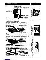
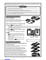
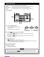
PARTS NAME OF REMOTE CONTROLLER
Display section
In the display example, all indicators are displayed for the explanation.
In reality only, the selected contents are displayed.
• When turning on the leak breaker for the first time, [SET DATA] flashes on
the display part of the remote controller. While this display is flashing, the
model is being automatically confirmed. After the [SET DATA] display has
disappeared, you may use the remote controller.
1
SET DATA display
Displayed during the setup of the timer.
2
Operation mode select display
The selected operation mode is displayed.
3
CHECK display
Displayed while the protective device works
or a fault/error occurs.
4
Timer time display
Time on the timer is displayed.
(When a fault/error occurs, the check code is
displayed.)
5
Timer setting setup display
When pushing the Timer setting button, the
display on the timer is selected in order of
[OFF]
→
[OFF] repeat OFF timer
→
[ON]
→
No display.
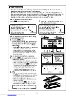
6
Filter display
If “FILTER
” is displayed, clean the air
filter.
7
TEST run display
Displayed during a test run.
8
Flap position display
(for 4-Way Air Discharge Cassette Type and
Under Ceiling Type model only)
Displays flap position.
9
SWING display
Displayed during the up/down movement of the
flap.
10
Set up temperature display
The selected set up temp. is displayed.
11
Remote controller sensor display
Displayed while the sensor on the remote
controller is used.
12
PRE-HEAT display
(for Heat-pump model only)
Displayed when the heating operation starts or a
defrost operation is carried out.
While this indication is displayed, the indoor fan
will stop or will go into LOW mode.
13
Operation ready display
Displayed when cooling or heating operation is
impossible because the outdoor temperature goes
out of the operable range.
14
No function display
Displayed if there is no function even when the
button is pushed.
15
Air volume select display
The selected air volume mode is displayed.
(AUTO)
(HIGH)
(MED.)
(LOW)
In the Concealed Duct High Static Pressure type
models, [HIGH] only is displayed for the air speed.
16
Mode select control display
Displayed when pushing the “Operation mode
select
” button while the operation mode is
fixed in heating or cooling mode by the system
manager of the air conditioner.
17
Central control display
Displayed when using the remote controller to-
gether with a central control remote controller.
If the Remote controller is prohibited at the central
control side,
flashes when operating the
ON / OFF
,
MODE
,
/
buttons. The change
will not be accepted.
(The contents available to be set up on the remote
controller differ according to the central control
mode. For details, refer to Owner’s Manual of the
central control remote controller.)
Содержание MMC-AP0151H
Страница 183: ...180 ...
Страница 204: ...201 ...
Страница 205: ...202 ...
Страница 208: ...205 MMK AP0071H AP0241H MMK AP0072H AP0122H ...
Страница 212: ...209 30 PRE DEF SWING ...
Страница 216: ...213 SWING FIX 1H 2H 2SH ...
Страница 217: ...214 1 2 3 4 5 ...
Страница 220: ...217 3mm ...
Страница 222: ...219 ...
Страница 223: ...220 ...
Страница 224: ...221 1 FAN 2 1 2 3 ...
Страница 225: ...222 MiNI SMMS MiNI SMMS 12 ...
Страница 226: ...223 5 C 43 C 21 C 32 C 15 C 24 C 15 C 15 5 C 15 C 28 C 80 1m ...
Страница 227: ...224 ON OFF ON ...
Страница 230: ...EH99924701 TOSHIBA CARRIER CORPORATION 2 CHOME 12 32 KONAN MINATOKU TOKYO 108 0075 JAPAN ...


