4. Schematic Wiring Diagrams
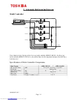
Multi Controllers
3 2 1
_
|_|
|_|
_
|_|
|_|
LD 1
LD 2
5 4 3 2 1
5 4 3 2 1
5 4 3 2 1
5 4 3 2 1
3 2 1
3 2 1
3 2 1
3 2 1
1 2 3
2
1
2
1
5
4
3
2
1
OUTDOOR
UNIT
INDOOR
UNIT D
INDOOR
UNIT C
INDOOR
UNIT B
INDOOR
UNIT A
COM
NO NC
2
1
Microswitch
1 2 3
1 2 3
1 2 3
1 2 3
1 2 3
1 2 3
1 2 3
1 2 3
1 2 3
1 2 3
Sump
Heater
Transformer
ThA
ThB
ThC
ThD
ThX
PMVA
PMVB
PMVC
PMVD
Float
Switch
PJ 10
PJ 6
PJ 7
PJ 8
PJ 9
PJ 1
PJ 2
PJ 3
PJ 4
PJ 5
PJ 16
PJ 14
PJ 13
PJ 12
Multi Controller P.C.
Board
MCC - 1210
Capacity Code
Swiches
Branch
A
Branch
B
Branch
C
Branch
D
Display
Switch
The colours used in this
diagram are not
representative of those on
the product, they are
intended to indicate the
status of each wire.
= 240v ac Live Wiring
= Neutral Wiring
= Serial Wiring
= Earth Wiring
= ac low voltage
= ac low voltage
RBM - Y1032E - E does not have
PMVD, ThD, indoor unit D connections
or the capacity code switch for branch D.
TP 1
TP 2
TOSHIBA
AUGUST 1997
Page 10


