


26
•
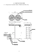
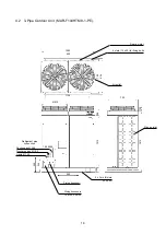
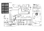
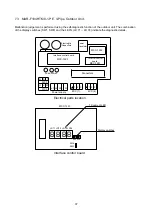
The dashed lines indicate wiring on site.
•
and
indicate terminal blocks, and numbers
within them are terminal numbers.
•
indicates a printed circuit board.
•
The
frame indicates the product body.
•
RBM-Y1034C-PE and RBM-Y1034-1-PE do not have
PMVD, ThD or the connection block for Indoor unit D.
The capacity rank code setting for unit D is to be set to "0".
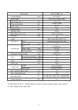
Part Name
Pulse modulating valve
Temperature sensor
Transformer
Float switch
Heater
Reset switch
Fault Indicator LED
Fuse (T1A)
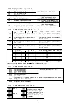
OUTDOOR
UNIT
Capacity
rank
setting
Display selector switch
INDOOR
UNIT D
INDOOR
UNIT A
INDOOR
UNIT B
INDOOR
UNIT C
7 Segment LED
Spark
killer
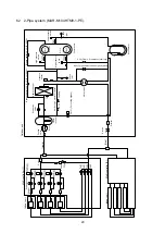
5.4
2-Pipe Multi Controller (RBM-Y1034C-PE, RBM-Y1044C-PE, RBM-Y1034-1-PE,
RBM-Y1044-1-PE).
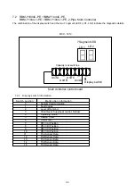
Symbol
PMV
A, B, C, D
Th
A, B, C, D, X
Tr
CS
H
MS
LD1, LD2
F
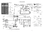
Control PC Board
Transformer
Terminal Plate
Parts layout
Reset
switch
A
B
C
D
Содержание MAR-C104M8-1-PE
Страница 2: ......
Страница 22: ......
Страница 58: ...61 13 EXPLODED VIEWS AND SERVICE PARTS LISTS 13 1 Outdoor Unit MAR C104M8 1 PE ...
Страница 60: ...63 13 3 Outdoor Units MAR M104HTM8 1 PE MAR F104HTM8 1 PE ...
Страница 63: ...66 13 6 Outdoor unit electrical parts assembly MAR C104M8 1 PE ...
Страница 65: ...68 MAR M104HTM8 1 PE MAR F104HTM8 1 PE ...
Страница 72: ......


