background image

3-1

SECTION 3

EXPLODED VIEWS AND PARTS LIST

SAFETY PRECAUTION

The parts identified by 

 mark are critical for safety. Replace only with part number specified.

The mounting position of replacement is to be identical with originals.

The substitute replacement parts which do not have the same safety characteristics are specified in the parts list
may create shock, fire or other hazards.

1. EXPLODED VIEWS

1-1. Packing Assembly (IK-TU51CU)

Y110

A701

A701A

Содержание IK-TU51CU

Страница 1: ...CCD CAMERA SERVICE MANUAL IK TU51CU JK TU52H JK TU53H FILE NO 210 200006 PRINTED IN JAPAN Oct 2000 S IK TU51CU JK TU52H JK TU53H ...

Страница 2: ... the fault must be located and corrected Repeat the above test with AC line reversed NEVER RETURN A CAMERA TO THE CUSTOMER WITHOUT TAKING NECESSARY CORRECTIVE ACTION READING SHOULD NOT EXCEED 0 3V Test all exposed metal Voltmeter Hook up for Leakage Current Check The lightning flash with arrowhead symbol within an equilateral triangle is intended to alert the user to the presence of uninsulated da...

Страница 3: ...ions 2 1 1 2 Total Adjustment 2 4 1 3 Partial Adjustment 2 7 SECTION 3 EXPLODED VIEWS AND PARTS LIST 1 EXPLODED VIEWS 3 1 1 1 Packing Assembly IK TU51CU 3 1 1 2 Packing Assembly JK TU52H JK TU53H 3 2 1 3 Chassis Assembly IK TU51CU 3 3 1 4 Camera Head Assembly JK TU52H 3 4 1 5 Camera Head Assembly JK TU53H 3 5 7 MODE SETTING BY ON SCREEN DISPLAY 1 7 8 BEFORE MAKING SERVICE CALL 1 24 9 SPECIFICATION...

Страница 4: ...1 1 SECTION 1 GENERAL DESCRIPTION IK TU51CU ...

Страница 5: ...1 2 ...

Страница 6: ...1 3 ...

Страница 7: ...1 4 ...

Страница 8: ...1 5 ...

Страница 9: ...1 6 ...

Страница 10: ...1 7 ...

Страница 11: ...1 8 ...

Страница 12: ...1 9 ...

Страница 13: ...1 10 ...

Страница 14: ...1 11 ...

Страница 15: ...1 12 ...

Страница 16: ...1 13 ...

Страница 17: ...1 14 ...

Страница 18: ...1 15 ...

Страница 19: ...1 16 ...

Страница 20: ...1 17 ...

Страница 21: ...1 18 ...

Страница 22: ...1 19 ...

Страница 23: ...1 20 ...

Страница 24: ...1 21 ...

Страница 25: ...1 22 ...

Страница 26: ...1 23 ...

Страница 27: ...1 24 ...

Страница 28: ...1 25 JK TU52H ...

Страница 29: ...1 26 ...

Страница 30: ...1 27 JK TU53H ...

Страница 31: ...1 28 ...

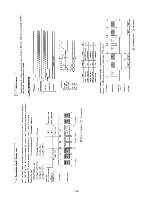
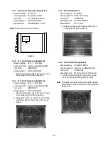
Страница 32: ...orrect Partial adjustment procedures are shown in the flow chart in the item 1 3 Adjust according to the flowchart otherwise the adjustment will be incorrect 1 1 Preparations 1 1 1 Equipment Required ACadaptor Waveformmonitor WFM Vector scope Frequencycounter Digital voltmeter Colormonitor Plastic chip screwdriver Lights TOSHIBA photo reflector lamp 500W x 2 or a halogen lamp 500W x 2 White paper ...

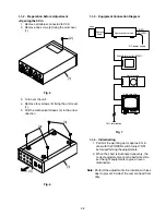
Страница 33: ... Initial Setting 1 Perform the warming up for approx 5 min utes with the POWER switch turned ON before performing the adjustments 2 When the chart is illuminated unevenly the correct adjustment cannot be performed So set the light equipments to give an even illumination Note Perform the adjustments in a location with less dust to prevent inside of the camera head from dirty Lens Camera head Camera...

Страница 34: ...5 Adjusting Locations Fig 8 Driver PC board Top side Fig 9 DSP PC board Bottom side PT01 DC DC TL01 RL52 RL51 RL50 PH03 PH02 1 2 1 Sub Carrier Frequency Adjustment CA50 SA01 ADJ NORM 1 2 11 Area Size Adjustment ...

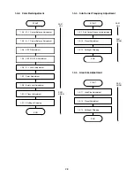
Страница 35: ... on the front panel and select the adjusting item Adjust the controls and electrical controls on each PC board The electrical controls are adjusted by the DATA buttons on the front panel Flowchart 1 2 1 Sub Carrier Frequency Adjustment 1 2 2 R Y Carrier Balance Adjustment 1 2 3 B Y Carrier Balance Adjustment 1 2 4 REF G Adjustment 1 2 5 REF R REF B Adjustment 1 2 6 B Y Level Adjustment 1 2 7 Color...

Страница 36: ... OUT Adjusting point DATAUP DOWN 1 Set the luminance spot of the vector scope at its center with the DATA buttons 2 Repeat the items 1 2 2 and 1 2 3 to set the luminance spot to the center of the vector scope 1 2 4 REF G Adjustment Screen display 04 REF G Test equipment WFM LPF mode Test point VIDEO OUT Adjusting point DATAUP DOWN Specification 60 1 IRE 1 Adjust the white level of the waveform to ...

Страница 37: ...r adjust the burst level of the waveform monitor to 40 1 IRE with the DATA buttons 1 2 9 ABB1 Adjustment Screen display 09 ABB1 1 Set the lens iris to close 2 Push the DATA buttons 3 The automatic black balance adjustment is performed automatically and ABB OK is displayed on the screen 1 2 10 ABB2 Adjustment Screen display 11 ABB2 1 Set the lens iris to close 2 Push the DATA buttons 3 The automati...

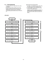
Страница 38: ...FILE A with the FILE button 1 2 13 Setting at Shipping POWER FRONT OFF KEY LOCK REAR OFF 1 3 Partial Adjustments In this chapter the adjustments required rela tively frequently are selected and associated items to be checked previously or to be adjusted before or after the adjustments are given in the flowchartbelow Be sure to perform the adjustments following to the flowchart Items shown within t...

Страница 39: ...REF R REF B Adjustment 1 2 6 B Y Level Adjustment 1 2 7 Color Adjustment 1 2 12 Preset Adjustment 1 2 13 Setting at Shipping START END SA01 ADJ SA01 NORM 1 2 8 Burst Level Adjustment 1 2 1 Sub Carrier Frequency Adjustment 1 2 12 Preset Adjustment 1 2 13 Setting at Shipping START END SA01 ADJ SA01 NORM 1 2 11 Area Size Adjustment 1 2 12 Preset Adjustment 1 2 13 Setting at Shipping START END SA01 NO...

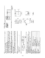
Страница 40: ...e only with part number specified The mounting position of replacement is to be identical with originals The substitute replacement parts which do not have the same safety characteristics are specified in the parts list may create shock fire or other hazards 1 EXPLODED VIEWS 1 1 Packing Assembly IK TU51CU Y110 A701 A701A ...

Страница 41: ...3 2 1 2 Packing Assembly JK TU52H JK TU53H Y110 A701 A702 ...

Страница 42: ...001 H001A UC01A UC01A UC01 UC02A A201A A201A A203A A203K A203K A203K PF01A PF01 UC05 UC05A A203 A201 A202 A202A A202A PC10A PC10 PC05 PC05 UC03 W003A W003 A204 A204A PK01 PK01A UC02 PC09 PC09 PC06 PC06 PC08 PC08 PC04 PC04 W002 A201 S001 A203A ...

Страница 43: ...3 4 1 4 Camera Head Assembly JK TU52H A110A A110A A116A A111A A111 A116 A110 A113 PF01 PF01 ...

Страница 44: ...3 5 1 5 Camera Head Assembly JK TU53H A113 A110 A110A PF01 PF01A PF01 A111 A111A A111A ...

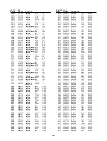
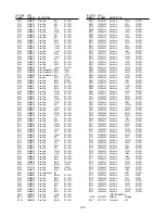
Страница 45: ...3 23314562 Transistor 2SC4176 QH14 A6031247 IC TC7SZ00FU QH15 A6031247 IC TC7SZ00FU QH17 23314558 Transistor 2SA1610 QH18 70114340 Transistor Chip UPA674T QH19 A6549570 Transistor Chip 2SA1586 Y QH20 A6365620 Transistor Chip 2SC4116 Y QH24 A6030681 IC TC7SH08FU QJ01 A6365620 Transistor Chip 2SC4116 Y QJ03 23314570 Transistor Chip UN5116 QJ05 23314558 Transistor 2SA1610 QJ06 23314558 Transistor 2SA...

Страница 46: ...Chip Tantalum10µF M 10V CJ02 24088979 Chip Cap Tantalum1µF M 25V CJ03 24109681 Cap Chip 680pF K50V CJ04 24092573 Cap Chip 0 47µF K16V CJ05 24088079 Cap Chip Tantalum10µF M 10V CJ06 24088079 Cap Chip Tantalum10µF M 10V CJ07 24088099 Cap Chip Tantalum10µF M 6 3V CJ08 24092730 Cap Chip 0 1µF K16V CJ09 24088099 Cap Chip Tantalum10µF M 6 3V CJ11 24105180 Cap Chip 18pF J50V CJ12 24092730 Cap Chip 0 1µF ...

Страница 47: ...kΩ D1 16W RB25 24998432 Res Chip 4 3kΩ D1 16W RB26 24998750 Res Chip 75kΩ D1 16W RB27 24998202 Res Chip 2kΩ D1 16W RB28 24998101 Res Chip 100Ω D1 16W RB29 24998560 Res Chip 56Ω D1 16W RB30 24998471 Res Chip 470Ω D1 16W RB32 24998270 Res Chip 27Ω D1 16W RD01 24998102 Res Chip 1kΩ D1 16W RD02 24998271 Res Chip 270Ω D1 16W RD03 24998752 Res Chip 7 5kΩ D1 16W RD04 24998102 Res Chip 1kΩ D1 16W RD05 249...

Страница 48: ...es Chip 15kΩ D1 16W RJ38 24998123 Res Chip 12kΩ D1 16W RJ39 24998821 Res Chip 820Ω D1 16W RJ40 24998103 Res Chip 10kΩ D1 16W RJ41 24998153 Res Chip 15kΩ D1 16W RJ42 24998202 Res Chip 2kΩ D1 16W RJ43 24998272 Res Chip 2 7kΩ D1 16W RJ44 24000445 Res ChipJumper 0Ω RJ46 24998203 Res Chip 20kΩ D1 16W RJ47 24998333 Res Chip 33kΩ D1 16W RJ48 24998333 Res Chip 33kΩ D1 16W RJ49 24000445 Res ChipJumper 0Ω R...

Страница 49: ...1 5kΩ D1 16W RR01 24998821 Res Chip 820Ω D1 16W RR02 24998334 Res Chip 330kΩ D1 16W LOCATION PART NUMBER NUMBER DESCRIPTION LOCATION PART NUMBER NUMBER DESCRIPTION RR03 24998392 Res Chip 3 9kΩ D1 16W RR04 24998202 Res Chip 2kΩ D1 16W RR05 24998821 Res Chip 820Ω D1 16W RR06 24998112 Res Chip 1 1kΩ D1 16W RR07 24998472 Res Chip 4 7kΩ D1 16W RR08 24998102 Res Chip 1kΩ D1 16W RR09 24998152 Res Chip 1 ...

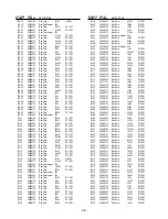
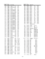
Страница 50: ...ION PART NUMBER NUMBER DESCRIPTION LOCATION PART NUMBER NUMBER DESCRIPTION QN05 23000482 IC MAX4330EUK QN06 23000481 IC AD9203ARU QN08 23000482 IC MAX4330EUK QN09 23000481 IC AD9203ARU QN10 23000499 IC XCS30XL 4TQ QN11 23000611 IC XC17S30XLV08 QN12 A6030695 IC TC7SH32FU DIODES DA03 23357218 Diode RD4 3MW DA04 23357218 Diode RD4 3MW DA05 23357218 Diode RD4 3MW DA06 23357218 Diode RD4 3MW DA07 23357...

Страница 51: ...M08 24998302 Res Chip 3kΩ D1 16W RM09 24998133 Cap Chip 13kΩ D1 16W RM10 24998203 Res Chip 20kΩ D1 16W RM11 24998752 Res Chip 7 5kΩ D1 16W RM12 24000445 Res ChipJumper 0Ω RM14 24998100 Res Chip 10Ω D1 16W RN01 24998821 Res Chip 820Ω D1 16W RN02 24998202 Res Chip 2kΩ D1 16W RN03 24998150 Res Chip 15Ω D1 16W RN04 24998512 Cap Chip 5 1kΩ D1 16W RN05 24998332 Res Chip 3 3kΩ D1 16W RN06 24998103 Res Ch...

Страница 52: ...A203 23540167 BottomCover BOTTOMCOVER A203A 70860194 FootRubber LEGSJ5012BL A204 23450281 RearPanel REARPANEL A204A 70391436 Screw 2x0 4x5mm A210A 70391436 Screw 2x0 4x5mm A701 70917916 Carton CARTONIK642H A701A 23564437 Label KOSOUBAKOIKTU51 H001 23122392 DC DC Converte DDU5074 H001A 23469291 Insulator INSULATOR PC04 70165208 Receptacle HR10A 7R 4PB PC05 70165277 Connector BNC DR D PC06 70165249 ...

Страница 53: ...4 1 SECTION 4 PC BOARDS AND SCHEMATIC DIAGRAMS 1 PC BOARDS 1 1 Front PC Board Soldering Side 1 2 DC PC Board Component Side Soldering Side ...

Страница 54: ...4 2 1 3 Rear PC Board IK 528A Component Side Soldering Side ...

Страница 55: ...4 3 1 4 Driver PC Board Component Side ...

Страница 56: ...4 4 Soldering Side ...

Страница 57: ...4 5 1 5 DSP PC Board Component Side ...

Страница 58: ...4 6 Soldering Side ...

Страница 59: ...4 7 2 BLOCK DIAGRAMS 2 1 Power Supply Block Diagram ...

Страница 60: ...2 2 TG SG Block Diagram 4 8 4 9 ...

Страница 61: ...2 3 Pre Process Block Diagram 4 10 4 11 ...

Страница 62: ...2 4 ENC Output Block Diagram 4 12 4 13 ...

Страница 63: ...2 5 DSP Block Diagram 4 14 4 15 ...

Страница 64: ...2 6 Memory Block Diagram 4 16 4 17 ...

Страница 65: ...4 1 2 7 Auto Block Diagram 4 18 ...

Страница 66: ...4 2 2 8 D Out Block Diagram 4 19 ...

Страница 67: ...4 20 4 21 3 CIRCUIT DIAGRAMS 3 1 Overall Wiring Diagram ...

Страница 68: ...4 22 4 23 3 2 Power Supply Circuit Diagram ...

Страница 69: ...3 3 TG Circuit Diagram 4 24 4 25 4 26 ...

Страница 70: ...4 27 4 28 4 29 3 4 SG Circuit Diagram ...

Страница 71: ...4 30 4 31 3 5 Pre Process Circuit Diagram ...

Страница 72: ...4 32 4 33 4 34 3 6 ENC Circuit Diagram ...

Страница 73: ...4 35 4 36 3 7 Output Circuit Diagram ...

Страница 74: ...4 37 4 38 4 39 3 8 DSP Circuit Diagram ...

Страница 75: ...4 40 4 41 4 42 3 9 Memory Circuit Diagram ...

Страница 76: ...4 43 4 44 3 10 Auto Circuit Diagram ...

Страница 77: ...4 45 4 46 3 11 D Out Circuit Diagram ...

Страница 78: ...4 1 3 12 Rear Circuit Diagram 4 47 ...

Страница 79: ...SECTION 5 SPECIFICATIONS 1 SPECIFICAIONS IK TU51CU JK TU52H JK TU53H ...

Страница 80: ......

Отзывы: