IK-TF5P
1-3
7
4.
CONNECTION
4
. 1
Standar
d
Connection
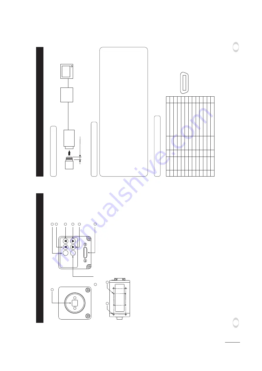
IK-TF5P
Lens
Cable (not included)
Frame grabber board,
image process
equipment etc.
Monitor
Less than 4 mm
DIGITAL Function
I/O
1
2
3
4
5
6
7
8
9
10
11
12
13
+12V
X0-
X1-
X2-
Xcllk-
X3-
SerTC+
SerTFG-
CC1-
CC2+
CC3-
CC4+
GND
14
15
16
17
18
19
20
21
22
23
24
25
26
–
O
O
O
O
O
I
O
I
I
I
I
–
GND
X0+
X1+
X2+
Xcllk+
X3+
SerTC-
CC1+
CC2-
CC3+
CC4-
Serial communication control (RXD)
Serial communication control (TXD)
Trigger pulse input
Partial scanning control
External HD input
External VD input
+12V
1
13
26
14
Connector used:
12226-51000-00
(3M) or equivalent.
4
.
2
Cautions on Connection
t
When connecting the camera cab
les
, be sure to unplug the po
wer source of the camer
a and the other
equipment connected.
t8
e suggest using a C mount lens made f
or a 3CCD camer
a.
When using another lens
, the best camer
a perf
or
mance of this camer
a ma
y not be obtained.
(F
or e
xample
, lo
w resolution ma
y occur
, f
ocus ma
y be lost through the r
ange of a z
oom lens
, and
flare, ghost or shading may occur)
Furthermore, in order to avoid damaging the mounting portion of the camera head, use a lens which
has projection dimension from the mounting base of less than 0.157"(4mm).
t
Supply the DC po
w
er supply (DC10V
-DC13V) of IK-TF5P camer
a from the pins 1 and 26 of the cab
le
(sold separ
ately).
t'
or DC po
w
er supply connecting to DIGIT
AL ter
minal, use the connector which type is applicab
le to
P
oCL standard.
4
.
3
Connector Pin Assignments
6
3.
NAMES AND FUNCTIONS
1
Pr
ism
fa
ceplate
The protection cap is attached on the lens mount por
tion.
After remo
ving the cap
,
mount the lens
. Be careful not to scr
atch or touch the optical area.
2
DISP b
utton
Used when s
witching the displa
y.
3
P
A
GE b
utton
Used when s
witching to the men
u and when selecting the men
us
.
4
MENU UP b
utton
MENU UP b
utton
Select the function to be confir
med or changed on the men
u.
5
MENU DO
WN b
utton
Select the function to be confir
med or changed on the men
u.
6
D
A
T
A
UP (A
WB) b
utton
Changes the v
alue of the function selected b
y
the MENU (UP/DO
WN) b
utton.
(Also
used when using A
W
B
.)
7
D
A
T
A
DO
WN b
utton
Changes the v
alue of the function selected b
y
the MENU (UP/DO
WN) b
utton.
8
DIGIT
AL ter
minal
8-bit RGB
, digital signal, and sync signal are output in the Camer
a Link f
o
rmat.
T
rigger signal and e
xter
nal sync signal (HD
,VD) are input.
Mode s
witching signal f
or par
tial scanning is input.
Accepts ser
ial comm
unication control signal, and accept a DC po
w
er input (12V).
9
Mounting holes M3
Used to mount the camer
a.
!
Mounting holes M2
Used to mount the camer
a.
DISP
PAGE
MENU
DATA
(AWB)
1
8
2
4
6
7
5
3
Prism faceplate
DIGITAL terminal
DISP button
PAGE button
[ Rear ]
[ Front ]
[ Bottom ]
MENU UP button
MENU DOWN button
DATA UP (AWB) button
DATA DOWN button
9
10
Содержание IK-TF5P
Страница 37: ...IK TF5P 4 1 SECTION 4 PC BOARDS AND SCHEMATIC DIAGRAMS 1 PC BOARDS Sub PC Board 1 1 Top Side Bottom Side ...
Страница 38: ...IK TF5P 4 2 Process PC Board 1 2 Top Side Bottom Side ...
Страница 39: ...IK TF5P 4 3 TG PC Board 1 3 Top Side Bottom Side ...
Страница 40: ...IK TF5P 4 4 Mother PC Board 1 4 Top Side ...
Страница 41: ...IK TF5P 4 5 Bottom Side ...
Страница 42: ...IK TF5P 4 6 Rear PC Board 1 5 Top Side Bottom Side ...
Страница 47: ...3 CIRCUIT DIAGRAMS 3 1 Overall Wiring Diagram 4 15 IK TF5P 4 16 ...
Страница 48: ...3 2 Sub Circuit Diagram 4 17 IK TF5P 4 18 ...
Страница 49: ...3 3 Process Circuit Diagram 3 3 1 Process Circuit Diagram 1 4 19 IK TF5P 4 20 ...
Страница 50: ...4 21 IK TF5P 4 22 3 3 Process Circuit Diagram 3 3 2 Process Circuit Diagram 2 ...
Страница 51: ...3 4 TG Circuit Diagram 4 23 IK TF5P 4 24 ...
Страница 52: ...3 5 Mother Circuit Diagram 3 5 1 Mother Circuit Diagram 1 4 25 IK TF5P 4 26 ...
Страница 53: ...3 5 Mother Circuit Diagram 3 5 2 Mother Circuit Diagram 2 4 27 IK TF5P 4 28 ...
Страница 54: ...3 6 Head Circuit Diagram 4 29 IK TF5P 4 30 ...
Страница 56: ......


