background image

37

11.6 Grounding configuration

This section describes the grounding configuration with AC input service entrance.

As inadequate grounding configuration causes problems on start-up, connections for the ground line

and the neutral line must be done properly according to the system configuration.

11.6.1 Recommended configuration with input neutral grounded

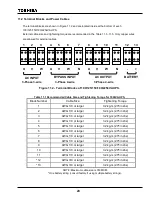
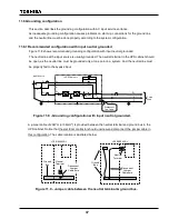
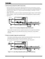
Figure 11.8 shows recommended grounding configuration with input neutral grounded.

The neutral line at the input source is usually grounded. The neutral terminal in the UPS cabinet should

be open, as the neutral line must be grounded only at one point in a system. And the neutral line must

be properly fed to the bypass input.

Figure 11.8 - Grounding configuration with input neutral grounded.

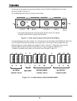
A jumper cable of 2AWG (or 38mm

2

) is provided between the neutral terminal and ground bus in the

UPS cabinet. Notice that the electrical contractor should unscrew and disconnect the jumper cable in

this configuration. The cable location is illustrated below.

Figure 11.9 - Jumper cable between the neutral terminal & ground bus.

N

G

3

φ

3

φ

3

φ

N

G

< UPS Cabinet >

N

3

φ

3

φ

G

Input Source

Disconnect
The Cable

Ground

Bus

Neutral

Terminal

Disconnect

Jumper

Cable here

< 100~225kVA >

Ground

Bus

Disconnect

Jumper

Cable here

< 250/300kVA >

Neutral

Terminal

G

N

3

φ

To the
Load

Содержание G8000 Series

Страница 1: ...ual carefully before installing the UPS Retain this manual with the UPS for easy reference when required This manual was written for the consulting engineer architect and electrical contractor TOSHIBA Corporation 2005 All Rights Reserved REQUIREMENT S Document Number 57490 000 February 2005 ...

Страница 2: ... all warranties and may void the UL CUL listing Unauthorized modifications can also result in personal injury death or destruction of the equipment 1 Introduction This manual is intended to help implement safe and correct transportation installation and wiring of the G8000 Series Uninterruptible Power System hereafter referred to UPS Before transportation installation and wiring of the UPS please ...

Страница 3: ...PS part is 36 months from the shipment date see TIC bill of lading Unless otherwise specified the warranty period for a UPS battery is 24 months from the shipment date see TIC bill of lading Please complete the following information and retain for your records Job Number Model Number Serial Number Application Shipment Date Installation Date Inspected By ...

Страница 4: ...l are registered trademarks of their respective owners Toshiba International Corporation TIC shall not be liable for direct indirect special or consequential damages resulting from the use of the information contained within this manual This manual is copyrighted No part of this manual may be photocopied or reproduced in any form without the prior written consent of Toshiba International Corporati...

Страница 5: ...y information that must be carefully adhered to The word DANGER preceded by the safety alert symbol indicates that an imminently hazardous situation exists that if not avoided will result in death or serious injury to personnel The word WARNING in capital letters preceded by the safety alert symbol indicates that a potentially hazardous situation exists that if not avoided could result in death or...

Страница 6: ...urces The minimum device ratings should be as follows Capacity Rated Input Breaker Rating Capacity Rated Input Breaker Rating 100kVA 480V 277Vac 480V 150A 125kVA 380V 220Vac 380V 250A 150kVA 480V 277Vac 480V 225A 180kVA 380V 220Vac 380V 350A 225kVA 480V 277Vac 480V 350A 250kVA 380V 220Vac 380V 500A 300kVA 480V 277Vac 480V 450A The maximum ambient temperatures in which the UPS should be operated is...

Страница 7: ...tandards or other ordinances Equipment equivalent to the above Equipment to supervise or control airways railways roads sea lanes or other transportation Equipment in nuclear power plants Equipment to control communications Equipment equivalent similar to the above mentioned Disclaimer In no event will Toshiba Corporation be responsible or liable for either indirect or consequential damage or inju...

Страница 8: ...e contact Toshiba if you need UPS modifications or plan to move the UPS Transportation WARNING When moving the UPS using a crane follow the specified work procedure and keep the suspension wire angle within 60 Moving the UPS by any method other than that specified may cause personal injury by being crushed or trapped by the UPS when it falls or overturns As per specification in chapter 8 When movi...

Страница 9: ...l Transportation Unpacking CAUTION Do not transport move store or place the UPS on its side Excessive force applied from heavy objects inside may damage the UPS Avoid vibration or shock exceeding 0 5G to the UPS Failing to observe this precaution may cause damage to the UPS When unpacking the unit do not give a direct shock or impact to the UPS with a hammer or disassembling tool It may cause dama...

Страница 10: ...ck Vibrations in the installation environment must have frequencies either lower than 10 Hz or higher than 20 Hz For vibrations under 10 Hz the acceleration due to those vibrations must not exceed 0 5 G For vibrations over 20 Hz and under 50 Hz the acceleration due to those vibrations must not exceed 0 5 G For vibrations over 50 Hz and under 100 Hz the total amplitude must not exceed 0 1 mm 6 Dust...

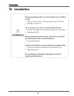
Страница 11: ...c electricity Make sure the air vents on the front and top of the UPS are NOT blocked Blocking the vents will cause the temperature inside the UPS to rise and may result in fire or UPS faults Do NOT install the UPS close to a water source It may cause electrical shock UPS fault or other accidents Please ask Toshiba or authorized representatives where the UPS and or components are to be disposed It...

Страница 12: ...ons or handling the wires observe the following precautions Do not forcibly bend or pull the wires or damage the insulation Do not place heavy objects on top of the UPS Failing to observe this precaution may damage the insulation of the wires or may cause a fire or an electric shock hazard Connect ground wire to the earth ground terminal only A missing ground wire may cause an electrical shock haz...

Страница 13: ... warning labels are placed in specified spots 2 Please read all warning labels and understand what they mean 3 Make sure warning labels are always legible Do NOT allow the labels to be removed or covered Locations of the Warning Labels 100 125 kVA Figure 5 1 100 125kVA UPS exterior interior showing warning labels ...

Страница 14: ...13 Figure 5 3 250 300kVA UPS exterior interior showing warning labels Locations of the Warning Labels 150 180 225 kVA Figure 5 2 150 180 225kVA UPS exterior interior showing warning labels ...

Страница 15: ... TIGHTENING TORQUE OF TERMINAL BLOCKS 1 2 3 4 5 6 7 8 9 10 11 12 13 U V W U V W N U V W N 380V 380V 380V 375V AC INPUT BYPASS INPUT AC OUTPUT BATTERY B RISK OF ELECTRIC SHOCK This UPS receive power from more than one source disconnection of all sources is required to de energize this unit before servicing Dangerous electric charge may be stored in capacitors and associated circuitry Wait at least ...

Страница 16: ...osure to a suitable grounding electrode in accordance with local code requirements I CAUTION RISK OF ELECTRIC SHOCK Heat Sink IGBT is not grounded Test before touching J CAUTION 8A control power source switch Do not turn off while operating K for 250kVA USE COPPER CONDUCTORS ONLY REFER TO INSTRUCTION MANUAL REGARDING TIGHTENING TORQUE OF TERMINAL BLOCKS 1 2 3 4 5 6 7 8 9 10 11 12 U V W U V W N U V...

Страница 17: ... and Weight 17 8 Transportation 20 8 1 Transportation by a crane 20 8 2 Transportation by a forklift 22 9 0 Storage 23 10 0 Installation 24 10 1 Unpacking 25 10 2 UPS Clearance 25 10 3 Anchor Bolts 26 11 0 Wiring 27 11 1 Overview 27 11 2 Terminal Blocks and Power Cables 28 11 3 External Breakers 34 11 4 Grounding Wire 35 11 5 Control Wires 36 11 6 Grounding configuration 37 ...

Страница 18: ... Figure 7 1 7 3 show the outline dimensions and weights of G8000 UPS Figure 7 1 100 125kVA UPS Exterior dimensions front right side 74 8 3 9 Earth Ground Bus 41 3 50 4 31 5 Weight 100kVA 1 000kg 2 200lbs 125kVA 1 200kg 2 640lbs ...

Страница 19: ...18 Figure 7 2 150 180 225kVA UPS Exterior dimensions front right side 55 1 31 5 46 74 8 3 9 Earth Ground Bus Weight 150kVA 1 200kg 2 640lbs 180 225kVA 1 500kg 3 300lbs ...

Страница 20: ...19 76 8 Weight 2 000kg 4 400lbs Earth Ground Bus Earth Ground Bus 74 8 3 9 35 4 Figure 7 3 250 300kVA UPS Exterior dimensions front right side ...

Страница 21: ...porting the UPS by using a crane follow the specified procedure and keep the suspension wire angle within 60 Moving the UPS by any method other than the specified may cause personal injury by being crushed or trapped by the UPS when it falls or overturns When transporting the UPS by a crane or a forklift truck follow the instructions below 8 1 Transportation by a crane Make sure that the suspensio...

Страница 22: ...PS Keep UPS level while lifting Minimize the impact of a sudden stop when lowering the UPS to a resting surface Figure 8 4 and 8 5 show examples of good and unacceptable operations Figure 8 4 Good operation Figure 8 5 Unacceptable operation More than 60deg Uneven Wires Figure 8 2 Angle more than 60 Figure 8 3 Uneven wires ...

Страница 23: ...gh to carry UPS Refer to chapter 7 Dimension and Weight for UPS weight Ensure that the UPS does not swing or tilt Then lift and transport the UPS Minimize the impact of a sudden stop when lowering the UPS to a resting surface Fix the forks up against the base If possible Insert the forks here Base 100 225kVA Insert the forks here 250 300kVA Figure 8 6 Transportation by a forklift ...

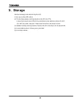
Страница 24: ...is 20 25 C 68 77 F In case this temperature is difficult to be maintained a temperature window of 0 40 C 32 104 F should be observed Temperature fluctuat ions should be minimal 3 Relative humidity at storing location should be 50 60 Humidity must not exceed 90 4 Avoid locations where corrosive gas is generated 5 Avoid dirty locations ...

Страница 25: ...e force applied from heavy objects placed inside of the cabinet may damage the UPS When unpacking the UPS do not give a direct shock or impact to the UPS using a hammer or disassembling tool It may damage the UPS Tighten anchor bolts to secure the UPS to the installation floor The UPS may fall during an earthquake if the anchor bolts are not installed and secured Ensure that there is adequate work...

Страница 26: ...lation 2 Make sure that exterior paint is not scratched and that the UPS cabinet is not damaged 3 Do not damage the UPS when using extracting tools 4 Do not remove the polyvinyl chloride cover if provided until installation 5 Packing materials should be disposed by the appropriate means after unpacking 6 In case of any abnormalities immediately report this information to Toshiba or authorized repr...

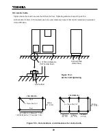
Страница 27: ...diameter are provided in the UPS base Figure 10 3 Hole locations and dimensions for anchor bolts 4 of 16mm diameter 5 8 screw holes Anchor Bolt 4 screw holes Side View Figure 10 2 Anchor bolt tightening Front Back 4 x 12mm Dia 1 2 550mm 21 21 32 100 125kVA 1 050mm 41 11 32 150 180 225kVA 1 170mm 46 1 16 100 225kVA 575mm 22 5 8 575mm 22 5 8 564mm 22 3 16 650mm 25 19 32 250 300kVA 8 x 12mm Dia 1 2 ...

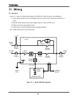
Страница 28: ...put and DC input 3 Earth ground wire at grounding electrode 4 Control wire terminal TB1 Battery cabinet and Bypass Breaker See corresponding section to each wiring term Figure 11 1 External Wiring Diagram Battery Breaker Battery Cabinet Bypass Breaker Bypass 3φ 4W Input Breaker AC Input 3φ 3W Output Breaker Output 3φ 4W DC input Bypass Contactor Contactor Thyristor Input Contactor Inverter Contact...

Страница 29: ...r larger 3 2 kg m 275 in lbs 3 AWG 1 0 or larger 3 2 kg m 275 in lbs 4 AWG 1 0 or larger 3 2 kg m 275 in lbs 5 AWG 1 0 or larger 3 2 kg m 275 in lbs 6 AWG 1 0 or larger 3 2 kg m 275 in lbs 7 AWG 1 0 or larger 3 2 kg m 275 in lbs 8 AWG 1 0 or larger 3 2 kg m 275 in lbs 9 AWG 1 0 or larger 3 2 kg m 275 in lbs 10 AWG 1 0 or larger 3 2 kg m 275 in lbs 11 AWG 1 0 or larger 3 2 kg m 275 in lbs 12 AWG 3 ...

Страница 30: ...um cable size is 350MCM One battery string consult factory if using multiple battery strings Table 11 3 Recommended Cable Size and Tightening Torque for 150kVA UPS Block Number Cable Size Tightening Torque 1 AWG 4 0 or larger 3 2 kg m 275 in lbs 2 AWG 4 0 or larger 3 2 kg m 275 in lbs 3 AWG 4 0 or larger 3 2 kg m 275 in lbs 4 AWG 4 0 or larger 3 2 kg m 275 in lbs 5 AWG 4 0 or larger 3 2 kg m 275 i...

Страница 31: ...E Maximum cable size is 350MCM Two battery strings or more consult factory if using one battery string Table 11 5 Recommended Cable Size and Tightening Torque for 225kVA UPS Block Number Cable Size Tightening Torque 1 Two 2 0 or larger 5 8 kg m 500 in lbs 2 Two 2 0 or larger 5 8 kg m 500 in lbs 3 Two 2 0 or larger 5 8 kg m 500 in lbs 4 Two 2 0 or larger 5 8 kg m 500 in lbs 5 Two 2 0 or larger 5 8 ...

Страница 32: ...00kVA UPS at the top The dashed line shows the side view of the screw holes The screws are used to tighten the lugs External cable size recommendations are located in Table 11 6 and 11 7 These tables show only the torque to tighten a terminal bus a corresponding lug Torque to tighten the cable end in a compression lug shall be specified by the lug vendor recommended in Table 11 8 Figure 11 4 Termi...

Страница 33: ...m cable size is 600MCM Two battery strings or more consult factory if using one battery string Table 11 7 Recommended Cable Size and Tightening Torque for 300kVA UPS Bus Number Cable Size Torque to tighten the terminal bus 1 Two 4 0 AWG or larger 2 5 4 5 kg m 215 386 in lbs 2 Two 4 0 AWG or larger 2 5 4 5 kg m 215 386 in lbs 3 Two 4 0 AWG or larger 2 5 4 5 kg m 215 386 in lbs 4 Three 350 MCM or la...

Страница 34: ... the top of the 250 300kVA UPS See Figure 11 5 for hole information The six holes must be punched during installation Four solid rectangles show the outline of the cable knockout plates The three dashed rectangles show the UPS opening under the plates Figure 11 5 Cable knockout plates at the top 250 300kVA 0 8 0 4 4 Dia 0 6 1 5 2 Dia 0 6 1 5 2 Dia Plate 2 Plate 3 Plate 1 Plate 4 Ground Wire AC Inp...

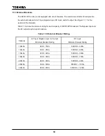
Страница 35: ...hows the minimum rating for each capacity of G8000 UPS breakers The Bypass input and the AC output require 4 pole breakers Table 11 9 External Breaker Rating Capacity AC input Bypass input AC output Minimum Breaker Rating DC input Minimum Breaker Rating 100kVA 480V 150A 500VDC 400A 125kVA 380V 250A 500VDC 600A 150kVA 480V 225A 500VDC 600A 180kVA 380V 350A 500VDC 750A 225kVA 480V 350A 500VDC 900A 2...

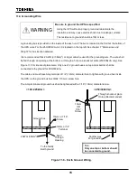
Страница 36: ...d through an opening at the bottom or through a hole on a knockout plate 250 300kVA only See Figure 11 5 for knockout plate detail Only one of 2 ground buses on top and at bottom shall be connected to the ground for 250 300kVA The cable end must have Amp terminal of 1 2 12mm diameter hole to tighten with ground bus inside the UPS as the ground bus has 33 64 13mm screw hole The Amp terminal and gro...

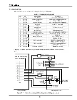
Страница 37: ...utput Signal Ground Ground for pin 1 5 10 12 Input P24 Battery s 13 Input Battery Overheat Overheat B contact 14 Output Bypass Breaker 15 Output 52C Trip Signal Shunt Trip Signal by EPO 16 Output Battery Breaker shunt trip 17 Output 72B Trip Signal by EPO or Battery shutdown 18 Output Battery breaker s 19 Output 72B Aux Contact Auxiliary A contact The UPS the battery cabinet and the bypass breaker...

Страница 38: ...n as the neutral line must be grounded only at one point in a system And the neutral line must be properly fed to the bypass input Figure 11 8 Grounding configuration with input neutral grounded A jumper cable of 2AWG or 38mm 2 is provided between the neutral terminal and ground bus in the UPS cabinet Notice that the electrical contractor should unscrew and disconnect the jumper cable in this conf...

Страница 39: ...nding configuration without input neutral If a ground fault interrupter is installed the system is likely to trip the interrupter during transferring to from the bypass circuit It is recommended to put 0 5 sec or longer delay on the ground fault interrupter 11 6 3 Recommended configuration with delta input If the input source has a delta connection 3 phase 3 wire without ground the neutral termina...

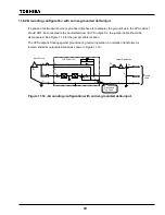
Страница 40: ...the jumper cable should be disconnected See Figure 11 9 for the jumper cable location The UPS output is floating against ground during normal operation An isolation transformer is recommended at output distribution as shown in Figure 11 12 Figure 11 12 Grounding configuration with corner grounded delta input N G 3 φ 3 φ 3 φ N G UPS Cabinet G N 3 φ 3 φ To the Load Output Distribution 3 φ 3 φ G Inpu...

Страница 41: ...ates Normal dot Title G8000 Installation Subject Author K Okizaki Keywords Comments Creation Date 01 19 05 1 00 PM Change Number 376 Last Saved On 02 07 05 7 12 AM Last Saved By Toshiba Total Editing Time 317 Minutes Last Printed On 02 07 05 8 47 AM As of Last Complete Printing Number of Pages 40 Number of Words 5 307 approx Number of Characters 30 252 approx ...

Отзывы: