background image

7.2. Reassembling Procedures

Step

Tool

42

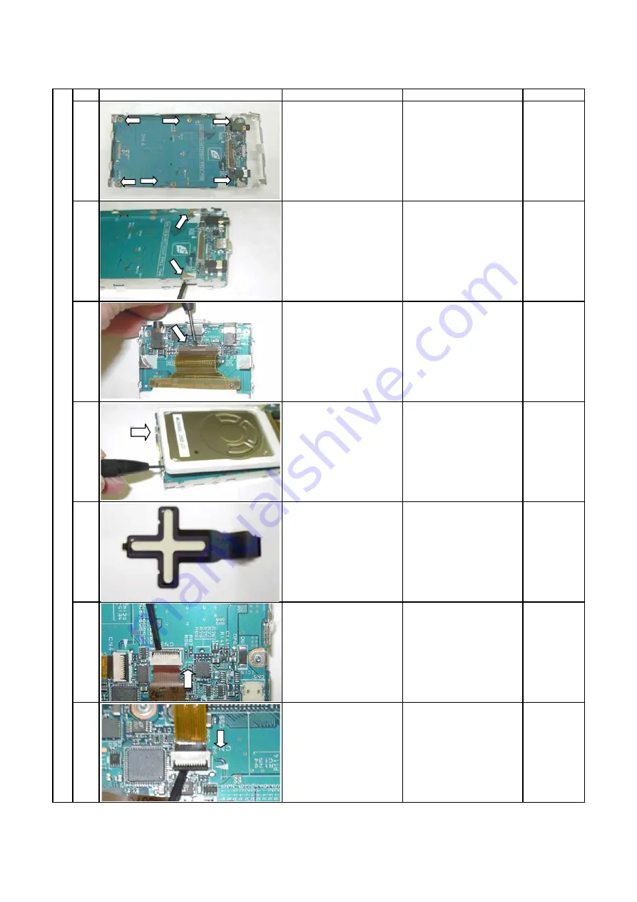
Reassembling Procedures

Photo

Description

Note

Fix the P.C. Board to
two frames.

Tighten six screws.

Insert the HDD cable
and push the lock lever
toward the P.C. Board to
lock it.

Confirm that the lock
lever is lifted up.

Install the cross key.

Phillips
screwdriver

Tighten two screws to fix
the frame.

Push the HDD in the
direction indicated by
the arrow and place it
inside the frame.

Screwdriver

Insert the cable from the
side panel SW into the
connector CN4 and
push the lock lever
toward the P.C. Board to
lock it.

Confirm that the lock
lever is lifted up and
released before
attachment.

Flathead
screwdriver

Insert the cross key into
the connector CN3 and
push the lock lever
toward the P.C. Board to
lock it.

Confirm that the lock
lever is lifted up and
released before
attachment.

Flathead
screwdriver

5

6

7

1

2

3

4

Содержание F Series

Страница 1: ...HDD AUDIO PLAYER SERVICE MANUAL MEGF60 MEGF40 MEGF20 MEGF10 UK FILE NO 400 200503 Jun 2005 5 MEGF60 ...

Страница 2: ...nt parts with same characteristics For safety sensitive parts specified by marking in circuit diagrams or parts lists use specified parts z After repair work is completed properly reassemble disassembled parts and securely reconnect cables as they were For safety reasons some insulating materials such as tubes and tapes are used and some parts are mounted with a gap from the board surface Furtherm...

Страница 3: ...uct in a thunderstorm Do not place the product near a magnet speaker or other object generating a magnetic field Do not place the product where it will be subject to strong vibrations Do not place or drop an object on the product Do not place the product where it will be exposed to water or high humidity Do not place a cup or other container of liquid near the product since spilled liquid may ente...

Страница 4: ...g the main board 22 3 5 Replacing the base 24 3 6 Replacing the frame 25 3 7 Replacing the LCD and LCD backlight unit 26 3 8 Replacing the lithium ion battery 27 3 9 Replacing the cradle 27 4 Troubleshooting 28 4 1 Anticipated defects 28 4 2 Defect analysis procedure as a maintenance service 29 5 Procedure to confirm the firmware version 36 6 About the version of firmware 36 7 Disassembling Reasse...

Страница 5: ...nternet according to the CDDB The HDD capacity ranges widely from 10 to 60GB The unit is compatible with SRS WOW A built in lithium ion rechargeable battery enables playback for about 16 consecutive hours The unit is compatible with a USB cradle enables transfer of music CDs with a single press of the RipRec button and also comes with a Line Out terminal 1 1 Product outline 1 1 1 Internal composit...

Страница 6: ...ns on a PC including TOSHIBA gigabeat room Owner s manual 1 1 3 Place for storing firmware Firmware is stored on FlashROM and HDD on the main board The GBSYSTEM folder on the HDD stores the firmware The GBSYSTEM folder comes with the SYSTEM and HIDDEN attributes Connecting it therefore does not allow it to be seen on the Explorer However reconfiguring the Explorer will enable it to be displayed In...

Страница 7: ...to PCM data is sent from the SDRAM to the DAC by the CPU The DAC converts the sent PCM musical data to analog format and outputs it to the headphones The CPU sets the volume control and equalizer levels on the DAC which controls the volume control level and equalizer levels according to the settings made 1 1 6 Transfer of musical data from the PC When the unit is connected to the PC by USB the Cyp...

Страница 8: ...KV Z DKV9KFVJ 75 5YKVEJ 615 75 6 TKFIG RTGUU 6 VCN 241 MDKV 6 6 456 GVE 2 1 75 KPK 75 K 5RGGF 2WUJ WVVQP 2 1 CEM 2614 6 6 2 1 75 8 4 75 8 6 6 2 1 0 75 8 6 6 2 1 0 176 126 10 6 6 2 1 0 6 6 2 1 5RGCMGT OR QPVTQN 2 1 4 10 1 2 1 TCFNG WVVQP Z 2 1 5NKFG 59 Z 2 1 75 156 8 6 6 2 8 06 00 0 0 1 5 2 2 2 1 2 2 3 2 2 1 1 2 3 4 45 QPN 6 QPN WH 7 46 6 5 6 QPN VJGT VTN 5 1 5 5 56 4 2 1 5 5 5 1 1 1 CVVGT JCTIGT 1...

Страница 9: ... 6 2 2 Power circuit block diagram ...

Страница 10: ... 3 2 Remove the AC adaptor and set the BATTERY switch to OFF Before disassembly be sure to remove the AC adaptor and set the BATTERY switch to OFF The gigabeat F series is such that its LCD and almost all ICs are powered even if the unit is turned off if it is powered by the AC adaptor or battery Before conducting a repair therefore the AC adaptor and battery must be removed Setting the BATTERY sw...

Страница 11: ...act Note that the HDD is vulnerable to impact Merely falling the HDD from a vertical position would give an impact exceeding the specifications 3 3 2 Holding the HDD When holding the HDD hold it at the following position Do not hold it at the following position ...

Страница 12: ...following steps to format the HDD 1 Connect the HDD to the gigabeat F series 2 Start Computer Management and select Disk Management 3 Make sure that the USB cable is connected to the PC then connect the USB cable to the gigabeat F series 4 Connect the AC adaptor to the gigabeat F series 5 Hold down the POWER button to turn on the gigabeat F series 6 Wait until the PC recognizes the gigabeat F seri...

Страница 13: ... 10 7 Right click Not Initialized displayed on Computer Management Then click Initialize Disk 8 Confirm that Disk in this case Disk 1 of the gigabeat F series is checked Then click OK ...

Страница 14: ... 11 9 Right click Unallocated displayed on Computer Management Then click New Partition ...

Страница 15: ... 12 10 The screen displays Welcome to the New Partition Wizard Click Next 11 In Select Partition Type confirm that Primary partition is selected Then click Next ...

Страница 16: ... 13 12 In Specify Partition Size confirm that the partition size is set to the maximum in this case 38139 Then click Next Confirm that the default is set to the maximum Click Next ...

Страница 17: ...ter or Path confirm that Assign the following drive letter is selected Then click Next The drive letter may be set to any value in this case E Confirm that the default is set to Assign the following drive letter Then click Next ...

Страница 18: ... 15 14 In Format Partition select Do not format this partition Then click Next The default is set to Format this partition with the following settings Select Do not format this partition Then click Next ...

Страница 19: ...15 The screen displays Completing the New Partition Wizard Click Finish A new partition will be created in about five seconds 16 Execute GBFormat exe GBFormat exe is in C Program Files TOSHIBA gigabeat room ...

Страница 20: ... 32KB Confirm that Perform a quick format is checked Then click Format 18 The screen displays a warning message Click OK 19 The formatting will be complete in about 15 seconds During the formatting the screen displays the progress bar as shown below 20 When the formatting is complete the screen displays something as shown below Click OK ...

Страница 21: ... 18 21 In Computer Management click Refresh Or you may press the F5 key ...

Страница 22: ... 19 22 Confirm that the disk is formatted with FAT32 Confirm that the disk capacity is equal to the partition size in this case 37 25GB ...

Страница 23: ...NU buttons connect the AC adaptor to the gigabeat F series This startup method updates the firmware During the update do not pull out the AC adaptor 33 When the firmware update is complete pull out the AC adaptor 34 Turn on the BATTERY switch 35 Connect the AC adaptor to the gigabeat F series 36 Hold down the POWER button 37 When the date and time configuration screen is displayed press the middle...

Страница 24: ...he commands specified below and add the SYSTEM and HIDDEN attributes to the GBSYSTEM attrib S H R E GBSYSTEM S D attrib S H R E GBSYSTEM 43 Close the command prompt 44 Execute 27 to 29 above and remove the USB cable from the gigabeat F series ...

Страница 25: ...series 5 Insert the CD ROM containing firmware into the CD ROM drive of the PC Note that the CD ROM used differs according to the model For the CD ROM refer to 6 About the version of firmware 6 Click Start All programs Accessories Command prompt to open the command prompt 7 At the command prompt execute the commands shown below where the CD ROM drive is D and the gigabeat F series is in E del Q E ...

Страница 26: ...ed on the Website If updating Ver 1 xx to Ver 2 xxx version upgrade is required for the PC software gigabeat room Confirm that the owner has gigabeat room 2 x for Ver 2 xxx and then update Ver 1 xx to Ver 2 xxx Connect the gigabeat F series to the PC 23 Start the Explorer If the HDD of the gigabeat F series contains the update folder delete it 24 Open the command prompt execute the commands specif...

Страница 27: ...ndicating the manufacturer s serial number of the unit In replacing the base remove the serial label and attach it to the new base 3 5 2 Installing the strap holder Fix the strap holder to the base with hot melt as shown in the figure below Circumference bottom 1 2 Circumference 5mm maximum ...

Страница 28: ... 25 3 6 Replacing the frame 3 6 1 Attaching the SW flexible cable and sheet switch Attach the SW flexible cable to the frame On top of it attach the sheet switch ...

Страница 29: ...ing the LCD and LCD backlight unit 3 7 1 Incorporating them into the LCD frame Peel off the protective film from the LCD and LCD backlight then incorporate them into the LCD frame Guard against fingerprints and dust ...

Страница 30: ... lithium ion battery as illustrated below 3 9 Replacing the cradle Note that the cradle comes in two types according to the thickness of the unit the capacity of the built in HDD Note also that for some models the cradle is optional not furnished with the unit For thinner models 30GB or less VENETIAN CRADLE MEGBCS13 For thicker models more than 30GB VENETIAN CRADLE MEGBCS14 ...

Страница 31: ...s 1 The unit will not turn on 2 No sound comes out 3 The sound is odd 4 The LCD display is odd 5 Operating the buttons on the unit does not work 6 Remote control does not work 7 A USB connection cannot be established 8 The battery cannot be recharged When battery powered the unit plays back only for a short time 9 HDD is not recognized 10 The unit cannot be recharged with the cradle ...

Страница 32: ...by holding down the POWER button for at least two seconds Replace the AC cord set AC adaptor main PCB assembly LCD or LCD backlight unit Repeat turning on the power and confirm that the headphones produce a beep Does the unit turn on Connect the remote controller to the unit release the HOLD switch of the remote controller and turn on the unit by using the remote controller by holding down the Pla...

Страница 33: ...ed from the previous page If the unit turns on successfully the owner may have set the BATTERY switch to OFF or have the battery discharged Therefore leave recharge the battery for at least four hours as it is then remove the AC adaptor and try turning on the unit Does the unit turn on Replace either the main PCB assembly or lithium ion battery ...

Страница 34: ... the Hold switch then turn on the unit by holding down the POWER button for at least two seconds Repeat turning on the power and confirm that the headphones produce a beep Is a beep heard Replace the main PCB assembly headphones or wired remote controller The unit may be set to a low sound level Check the level and see if the unit produces sound ...

Страница 35: ...r that the source data on the PC is defective and that the defect is not in the unit Replace the main PCB assembly headphones or wired remote controller Replace the main PCB assembly LCD or LCD backlight unit If the problem is with the buttons on the side of the unit Replace the SW flexible cable sheet switch or main PCB assembly If the problem is with the Puls Touch Replace either the feather tou...

Страница 36: ...N Set the BATTERY switch to ON See Charging the built in Battery in the Owner s Manual Connect the AC adaptor to the unit Check if the LCD displays the charging icon a picture of a power plug Does the unit display the charging icon red If the unit displays the charging icon the owner may have set the BATTERY switch to OFF or have the battery discharged Therefore leave recharge the battery for at l...

Страница 37: ... the message says Cannot access the HDD Replace either the HDD flexible cable or the main PCB assembly Does the unit display an error message If the message says The disk format is not supported Format the HDD See 3 3 3 Formatting the HDD and transferring and updating the firmware Replace the HDD The repair is complete ...

Страница 38: ...adaptor to the unit Try recharging the unit without the cradle Check if the LCD displays the charging icon a picture of a power plug Does the unit display the charging icon N Y Repair the unit according to 4 2 8 The battery cannot be recharged When battery powered the unit plays back only for a short time Replace either the cradle or the main PCB assembly ...

Страница 39: ... such as the problem that transferred music cannot be heard When updating the firmware proper firmware version should be used in consideration of the combination If the firmware version of the unit cannot be confirmed because of the board or HDD failure refer to the Model Name in the table below and judge which version of BootFlashROM Writing Tool CD should be used CD ROM Version Label Color gigab...

Страница 40: ...d to the gigabeat by the AC adapter or BATTERY the LCD and almost all the ICs are powered even during power OFF Therefore the AC adapter and BATTERY must be disconnected before repairing the gigabeat When the BATTERY button is set to OFF power supply from the BATTERY is shut off and all the settings become default This is the same state as where the BATTERY is disconnected ...

Страница 41: ...rrow The lock will be released and the upper gap will be made Release the center lock and remove the top panel Insert the flathead screwdriver between the side panel and top panel Lift up the top panel by pushing the screwdriver Screwdriver blade width about 1 8mm Insert the flathead screwdriver into the gap Similarly remove the bottom panel 2 㪈 6 5 4 3 ...

Страница 42: ...move the rear panel with the same procedure as the front panel Remove four screws fixing the front and rear panels Phillips screwdriver Remove the front panel Remove the cross key from the front panel Hold the cross key and lift up the front panel Remove the LCD Lift up the LCD frame Remove the side panel Hold the main unit by hand slide the side panel in the direction indicated by the arrow and t...

Страница 43: ...d screwdriver and release the lock Flathead screwdriver Lift up the PJ2 connector with the flathead screwdriver and disconnect it Flathead screwdriver Release the lock of the connector section and disconnect the cable from the side panel SW CN4 Lift up the lock lever black of the connector with the flathead screwdriver and release the lock Flathead screwdriver Remove the HDD Insert the flathead sc...

Страница 44: ...wdriver A view of the HDD removed from the chassis frame Disassembling Procedures Photo Description Note Disconnect the cable from the connector and remove the HDD Lift up the lock lever of CN1 and release the lock Remove the P C Board Remove two screws from the frame fixing the P C Board A view of the P C Board removed from the frame 23 22 21 27 26 25 24 ...

Страница 45: ...x the frame Push the HDD in the direction indicated by the arrow and place it inside the frame Screwdriver Insert the cable from the side panel SW into the connector CN4 and push the lock lever toward the P C Board to lock it Confirm that the lock lever is lifted up and released before attachment Flathead screwdriver Insert the cross key into the connector CN3 and push the lock lever toward the P ...

Страница 46: ...y Reassembling Procedures Photo Description Note Connect the battery to the connector CN5 Draw the battery cable not to touch the screw fixing the P C Board Position and insert the cable PJ2 from the LCD Insert it fully Insert the frame Assembly Insert the headphone terminal section and then insert the cradle connection terminal section 12 13 14 8 9 10 11 ...

Страница 47: ...operating Slide the front cover in the direction indicated by the arrow with the lock guide aligned and then fix it Install the top cover Fix the lock of one side and press it with your finger Install the rear cover Slide the rear cover in the direction indicated by the arrow with the lock guide aligned and then fix it Fix the front and rear covers Tighten four screws Phillips screwdriver The asse...

Страница 48: ...E A B 1 28 36 24 6 d b c a 11 35 23 22 30 50 50 50 50 50 25 50 50 50 37 37 38 33 38 21 32 50 50 13 2 20 31 6 26 12 6 6 100 105 106 110 111 113 115 101 102 103 104 MEGF40 60 MEGF40 60 MEGF40 60 MEGF10 20 8 Exploded view 45 ...

Страница 49: ... 26 P000433620 PM0019241100A FRAME ASSY ALL Seet Switch is attached 28 P000424890 G83C0004Q110 FEATHER TOUCH SENSOR SMK010004A ALL 30 P000425100 PM0019238100 LCD FRAME ALL 31 P000425110 PM0019239100 SWITCH BUTTON ALL 32 P000425120 PM0019240100 HDD RUBBER ALL 33 P000441720 PM0019547100 HDD SPACER 40S 60S 35 P000425140 PM0019243100 REAR PLATE ALL 36 P000441730 PM0020203100 BATTERY RUBBER ALL 37 P000...

Страница 50: ...ox 16 hours Built in battery Assuming 128 kbps 44 1 kHz WMA tracks excluding content protected with Windows Media DRM 10 in normal temperature 25 C backlight unlit volume adjusted to center The continuous playback time is a reference value but is not guaranteed since the actual playback time will vary depending on the operating condition ambient operating temperature the number of times the built ...

Страница 51: ...t rate Tracks with another combination may not play properly MP3 stereo Sampling frequency 22 05 44 1 48 kHz Bit rate 32 to 320 kbps MP3 mono Sampling frequency 22 05 44 1 48 kHz Bit rate 16 to 64 kbps WMA stereo Sampling frequency 22 05 44 1 kHz Bit rate 32 48 to 192 kbps WMA mono Sampling frequency 44 1 kHz Bit rate 32 kbps WAV stereo mono Sampling frequency 22 05 44 1 48 kHz Bits 16 bits This p...

Страница 52: ...when the OS upgrade is completed The user must log in as Administrator to use gigabeat room in Windows XP Home Edition or Windows XP Professional TOSHIBA cannot guarantee that the gigabeat room will function properly in a dual CPU system running Windows XP Professional or with Windows XP Home Edition Professional in a system incorporating an Intel Pentium 4 processor using Hyper Threading Technolo...

Страница 53: ...1 1 SHIBAURA 1 CHOME MINATO KU TOKYO 105 8001 JAPAN ...

Отзывы: