


5
May 2006 © TOSHIBA TEC
e-STUDIO2500c/3500c/3510c CONTROL PANEL
5 - 1
5. CONTROL PANEL
5.1
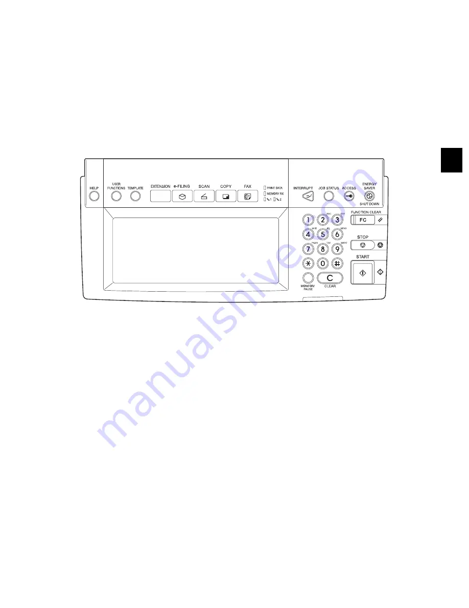
General Description
The control panel consists of button switches and touch-panel switches to operate the equipment and
select various modes, and LEDs and an LCD to display the state of the equipment or the messages.
When the operator’s attention is required, graphic symbols light or blink with messages explaining the
condition of the equipment in the LCD panel. When paper jams and “Call for service” occur, error codes
are also displayed to notify users of the problem.
A color LCD is used in this equipment so that visibility and operability are improved.
Fig. 5-1
Содержание e-STUDIO2500c
Страница 130: ...e STUDIO2500c 3500c 3510c CONTROL PANEL May 2006 TOSHIBA TEC 5 18 ...
Страница 158: ...e STUDIO2500c 3500c 3510c SCANNER May 2006 TOSHIBA TEC 6 28 ...
Страница 168: ...e STUDIO2500c 3500c 3510c IMAGE PROCESSING May 2006 TOSHIBA TEC 7 10 ...
Страница 188: ...e STUDIO2500c 3500c 3510c DRIVE SYSTEM May 2006 TOSHIBA TEC 9 2 ...
Страница 232: ...e STUDIO2500c 3500c 3510c PAPER FEEDING SYSTEM May 2006 TOSHIBA TEC 10 44 ...
Страница 256: ...e STUDIO2500c 3500c 3510c PROCESS UNIT RELATED SECTION May 2006 TOSHIBA TEC 11 24 ...
Страница 288: ...e STUDIO2500c 3500c 3510c DEVELOPER UNIT May 2006 TOSHIBA TEC 12 32 ...
Страница 395: ...18 May 2006 TOSHIBA TEC e STUDIO2500c 3500c 3510c PC BOARDS 18 1 18 PC BOARDS 1 PWA F SYS Fig 18 1 ...
Страница 396: ...e STUDIO2500c 3500c 3510c PC BOARDS May 2006 TOSHIBA TEC 18 2 2 PWA F IMG Fig 18 2 3 PWA F LGC Fig 18 3 ...
Страница 397: ...18 May 2006 TOSHIBA TEC e STUDIO2500c 3500c 3510c PC BOARDS 18 3 4 PWA F JSP Fig 18 4 5 PWA F USB Fig 18 5 ...
Страница 398: ...e STUDIO2500c 3500c 3510c PC BOARDS May 2006 TOSHIBA TEC 18 4 6 PWA F CCD Fig 18 6 7 PWA F SLG Fig 18 7 ...
Страница 400: ...e STUDIO2500c 3500c 3510c PC BOARDS May 2006 TOSHIBA TEC 18 6 11 PWA F EPU Fig 18 11 12 PWA F FIL Fig 18 12 ...
Страница 401: ......
Страница 402: ......