
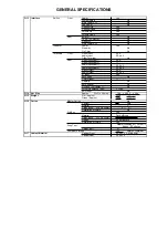

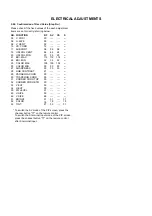


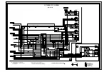

ELECTRICAL ADJUSTMENTS
2-22: PIP AFT
1.
2.
3.
4.
5.
Place the set with Aging Test for more than 15 minutes.
Receive the VHF HIGH on the PIP screen.
Connect the digital voltmeter to the TP052.
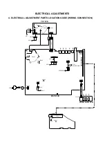
Activate the adjustment mode display of Fig. 1-1 and
press the channel button (54) on the remote control to
select “VCO”.
Adjust the L258 until the digital voltmeter is 2.5
±
0.5V.
2-23: PIP AGC
1.
2.
3.
4.
Place the set with Aging Test for more than 15 minutes.
Receive the VHF HIGH (63dB) on the PIP screen.
Connect the digital voltmeter to the TP051.
Adjust the VR251 until the digital voltmeter is 1.7
±
0.05V.
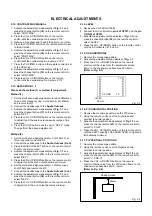
2-18: PIP VERTICAL POSITION L
1.
2.
3.
4.
Receive the monoscope pattern.
Using the remote control, set the brightness and
contrast to normal position.
Activate the adjustment mode display of Fig. 1-1 and
press the channel button (42) on the remote control to
select "V. POS L".
Press the VOL. UP/DOWN button on the remote
control until the value from the PIP screen frame to the
shadow mask becomes 20(+5, -0)mm.
(Refer to Fig. 2-5)
Fig. 2-5
Shadow mask
20mm
2-19: PIP HORIZONTAL POSITION L
1.
2.
3.
4.
Receive the monoscope pattern.
Using the remote control, set the brightness and
contrast to normal position.
Activate the adjustment mode display of Fig. 1-1 and
press the channel button (43) on the remote control to
select "H. POSI".
Press the VOL. UP/DOWN button on the remote
control until the value from the PIP screen frame to the
shadow mask becomes 35(+5, -0)mm.
(Refer to Fig. 2-6)
2-20: PIP HORIZONTAL POSITION R
1.
2.
3.
4.
Receive the monoscope pattern.
Using the remote control, set the brightness and
contrast to normal position.
Activate the adjustment mode display of Fig. 1-1 and
press the channel button (44) on the remote control to
select "H. POS R".
Press the VOL. UP/DOWN button on the remote
control until the value from the PIP screen frame to the
shadow mask becomes 35(+5, -0)mm.
(Refer to Fig. 2-7)
Fig. 2-6
Shadow mask
35mm
Fig. 2-7
35mm
Shadow mask
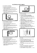
2-21: PIP R, G, B LEVEL
1.
2.
3.
4.
5.
6.
7.
8.
9.
10.
11.
Set condition is TV MODE without signal.
Connect the oscilloscope to pin 16 of IC751.
Activate the adjustment mode display of Fig. 1-1 and
press the channel button (48) on the remote control to
select "R".
Press the VOL. UP/DOWN button on the remote control
until the waveform value becomes 0.9
±
0.04V.
(Refer to Fig. 2-8)
Connect the oscilloscope to pin 11 of IC751.
Press the CH UP button once to set to "G" mode.
Press the VOL. UP/DOWN button on the remote control
until the waveform value becomes 0.9
±
0.04V.
(Refer to Fig. 2-8)
Press the VOL. DOWN button on the remote control to
decrease the step numbers by 2 steps.
Connect the oscilloscope to pin 8 of IC751.
Press the CH UP button once to set to "B" mode.
Press the VOL. UP/DOWN button on the remote control
until the waveform value becomes 0.9
±
0.04V.
(Refer to Fig. 2-8)
Fig. 2-8
0.9V


