background image

Toshiba

– 15 –

Outdoor Unit

Installation Manual

8

EVACUATE AND DEHYDRATE THE 

SYSTEM

CAUTION

UNIT DAMAGE HAZARD

Failure to follow this caution may result in equipment 
damage or improper operation.
Never use the system compressor as a vacuum pump.

Refrigerant tubes and indoor heat exchanger should 
be evacuated using the recommended deep vacuum 
method of 500 microns. The alternate triple evacuation 
method may be used if the procedure outlined below is 
followed. Always break a vacuum with dry nitrogen.

„

SYSTEM VACUUM AND 
CHARGE

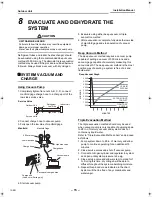
Using Vacuum Pump

1. Completely tighten flare nuts A, B, C, D, connect 

manifold gage charge hose to a charge port of the 
low side service valve.

2. Connect charge hose to vacuum pump.
3. Fully open the low side of manifold gage.

4. Start vacuum pump.

5. Evacuate using either deep vacuum or triple 

evacuation method.

6. After evacuation is complete, fully close the low side 

of manifold gage and stop operation of vacuum 
pump.

Deep Vacuum Method

The deep vacuum method requires a vacuum pump 
capable of pulling a vacuum of 500 microns and a 
vacuum gage capable of accurately measuring this 
vacuum depth. The deep vacuum method is the most 
positive way of assuring a system is free of air and 
liquid water.

Triple Evacuation Method

The triple evacuation method should only be used 
when vacuum pump is only capable of pumping down 
to 28 in. of mercury vacuum and system does not 
contain any liquid water.
Refer to “Triple Evacuation Method chart” and proceed 
as follows:
1. Pump system down to 28 in. of mercury and allow 

pump to continue operating for an additional 15 
minutes.

2. Close service valves and shut off vacuum pump.
3. Connect a nitrogen cylinder and regulator to system 

and open until system pressure is 2 psig.

4. Close service valve and allow system to stand for 1 

hr. During this time, dry nitrogen will be able to 
diffuse throughout the system absorbing moisture.

5. Repeat this procedure as indicated in the chart.

System will then be free of any cotaminants and 
water vapor.

Service Valve

Indoor Unit

C

D

A

B

Refrigerant

Low Side

High Side

Outdoor Unit

Service Valve

Manifold

500 microns

Manifold Gage

Low side valve

Charge hose

High side valve

Charge hose

Vacuum pump

Packed valve at gas side

Charge port

(Valve core (Setting pin))

500

0

1000

1500

2000

2500

3000

3500

4000

4500

5000

1

2

3

4

5

6

7

LEAK IN

SYSTEM

VACUUM TIGHT

TOO WET

TIGHT DRY

SYSTEM

Deep Vacuum Graph

MICR

ONS

MINUTES

15-EN

+00EH99865301_00Ta.book  Page 15  Wednesday, November 25, 2009  11:05 AM

Содержание CARRIER RAV-SP180AT2-UL

Страница 1: ...ançais Installation manual For OUTDOOR USE only Not accessible to the general public Vente interdite au grand public Kein öffentlicher Zugang Non accessibile a clienti generici No destinado al público en general Não acessível ao público em geral Niet geschikt voor huishoudelijk gebruik Μη προσβάσιμο από το γενικό κοινό Недоступен для посторонних Genel erişime açık değildir ...

Страница 2: ...THE SYSTEM 15 9 FINISHING 17 10 TEST RUN 17 11 PERIODIC MAINTENANCE 17 12 UNIT PUMP DOWN 18 13 POWER SAVE 18 Please read this Installation Manual carefully before installing the Air Conditioner This Manual describes the installation method of the outdoor unit For installation of the indoor unit refer to the Installation Manual attached to the indoor unit ADOPTION OF NEW REFRIGERANT This Air Condit...

Страница 3: ... 4 3 108 2 7 69 30 7 780 2 51 17 7 449 0 2 5 19 1 486 1 3 33 12 306 12 6 320 23 6 600 3 5 90 2 1 54 4 9 125 4 3 108 0 6 16 6 2 157 3 1 79 0 8 21 13 5 342 2 53 6 1 155 5 7 145 A legs Drain hole 2 Ø0 7 20 3 5 88 long hole 23 6 600 12 6 320 23 6 600 Drain hole Ø1 25 8 Ø0 2 6 hole 2 Ø0 4 11 0 6 14 long hole For fixing outdoor unit For Ø0 3 8 0 4 10 anchor bolts For Ø0 3 8 0 4 10 anchor bolts 2 Ø0 4 11...

Страница 4: ...on Manual 2 ACCESSORY PARTS NOTE Use drain nipple and waterproof rubber cap as necessary Part name Q ty Shape Usage Installation manual 1 This manual Hand this directly to the customer Drain nipple 1 Waterproof rubber cap 2 3 EN ...

Страница 5: ...d to the outdoor unit The field supplied connecting cables from the outdoor unit to the indoor unit consist for 4 wires and provides the power for the indoor unit as well as the communication signal between the outdoor and indoor unit Consult local building codes NEC National Electrical Code or CEC Canadian Electrical Code for special requirements The following are the electrical requirements Allo...

Страница 6: ...shock or fire Be sure to ground the equipment Improper grounding may cause an electric shock Do not connect ground wires to gas pipes water pipes lightning rods or ground wires for telephone wires Turn off the circuit breaker before attempting any electrical work and maintenance Make sure the circuit breaker is off Failure to do so may cause electric shock Use an exclusive power circuit for the ai...

Страница 7: ...efrigerant pipe the compressor sucks air and the refrigeration cycle is over pressurized which may cause a burst or injury When carrying out the pump down work shut down the compressor before disconnecting the refrigerant pipe Disconnecting the refrigerant pipe with the service valve left open and with the compressor still operating will cause air etc to be sucked in raising the pressure inside th...

Страница 8: ...are different from those of the conventional refrigerant units Accordingly special tools are required for the new refrigerant R410A units For connecting pipes use new and clean piping materials with high pressure fittings made for R410A only so that water and or dust does not enter Required Tools Equipment and Precautions for Use Prepare the tools and equipment listed in the following table before...

Страница 9: ...organic solvent is used A location where high frequency equipment including inverter equipment private power generator medical equipment and communication equipment is used Installation in such a location may cause malfunction of the air conditioner abnormal control or problems due to noise from such equipment A location in which the discharged air of the outdoor unit blows against the window of a...

Страница 10: ...allation 2 Multiple units installation Barrier also above unit 5 9 150 or more The height of the barrier should be lower than the height of the outdoor unit 7 9 200 or more 5 9 150 or more 11 8 300 or more The height of the obstacle should be lower than the height of the outdoor unit 5 9 150 or more 11 8 300 or more 11 8 300 or more 11 8 300 or more 7 9 200 or more 19 7 500 or more 5 9 150 or more...

Страница 11: ...eck the strength and horizontal of the base so that abnormal sounds do not emanate According to the following base diagram fix the base firmly with the anchor bolts Anchor bolt nut 3 8 M10 x 4 pairs 1 Field fabricate a snow or an ice stand for the unit using the above dimension 2 Place snow or ice stand on a foundation pad and secure it to the foundation pad and secure it to the foundation pad by ...

Страница 12: ...nt water from leaking Some conditions may cause condensation or dripping of water When collectively draining discharged water completely use a drain pan For Reference If a heating operation is to be continuously performed for a long time under the condition that the outdoor temperature is 32 F 0 C or lower draining defrosted water may be difficult due to the bottom plate freezing resulting in trou...

Страница 13: ...size A Unit in mm In case of flaring for R410A with the conventional flare tool pull the tool out approx 0 02 0 5 mm more than that for R22 to adjust it to the specified flare size The copper pipe gauge is useful for adjusting the projection margin size Tightening of Flare Connections 1 Align the centers of the flare connections and fully tighten the flare nuts with your fingers 2 Use two wrenches...

Страница 14: ...cessive torque the nut may break according to some installation conditions Pressure of R410A is higher than that of R22 Approx 1 6 times Therefore using a torque wrench tighten the flare pipe connecting sections that connect the indoor outdoor units at the specified tightening torque Incomplete connections may cause not only a gas leak but also trouble with the refrigeration cycle Do not apply ref...

Страница 15: ... show field wiring Connect the indoor outdoor connecting wires to the identical terminal numbers on the terminal block of each unit Incorrect connection may cause a failure 1 With the valve cover removed the electrical control box is exposed the side of the unit 2 Terminate the field wiring conduit if used at the conduit connection holes provided 3 Route the field power wires and the system interc...

Страница 16: ...uum depth The deep vacuum method is the most positive way of assuring a system is free of air and liquid water Triple Evacuation Method The triple evacuation method should only be used when vacuum pump is only capable of pumping down to 28 in of mercury vacuum and system does not contain any liquid water Refer to Triple Evacuation Method chart and proceed as follows 1 Pump system down to 28 in of ...

Страница 17: ...valve is fully opened after the screwdriver has reached the stopper do not apply torque exceeding 4 ft lbs 5 N m Applying excessive torque may damage the valve Valve handling precautions Open the valve stem until it reaches the stop It is unnecessary to apply further force Securely tighten the cap with a torque wrench Cap tightening torque EVACUATE BREAK VACUUM WITH DRY NITROGEN WAIT EVACUATE BREA...

Страница 18: ... with the valve closed the outdoor unit will become over pressurized which may damage the compressor or other components If there is a leak at a connection air can be sucked in and the internal pressure further increases which may cause a burst or injury Operate the air conditioner using the correct procedure as specified in the Owner s Manual 11PERIODIC MAINTENANCE For an air conditioning system ...

Страница 19: ...completion of pump down the unit close the valve and press refrigerant recovery switch for at least 2 second to stop operation 6 Turn off the power DANGER Be careful of electric shock because the P C board has an electrical current running through it 13POWER SAVE Power save can be set by setting SW801 dip switch Procedure 1 Turn on the SW801 dip switch 2 to activate Power save Power save controls ...

Страница 20: ...EH99865301 ...
Отзывы: