


– 19 –
10
Troubleshooting
Confirmation and check
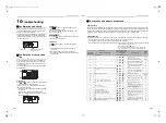
When a problem occurred in the air conditioner, the
check code and the indoor UNIT No. appear on the
display part of the remote control.
The check code is only displayed during the operation.
If the display disappears, operate the air conditioner
according to the following “Confirmation of check code
log” for confirmation.
Confirmation of check code
log
When a problem occurred on the air conditioner, the
check code log can be confirmed with the following
procedure. (The check code log is stored in memory up
to 4 check code.)
The log can be confirmed from both operating status
and stop status.
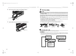
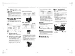
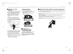
Procedure
1
Push
and
buttons simultaneously for 4 seconds
or more, the following display appears.
If [Service check]
is displayed, the mode enters in
the check code log mode.
• [
01
: Order of check code log] is displayed in CODE
No. window.
• [Check code] is displayed in CHECK window.
• [Indoor unit address in which a problem occurred] is
displayed in Unit No.
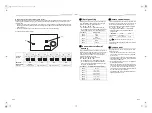
Procedure
2
Push
button. The check code log stored in
memory is displayed in order.
The numbers in CODE No. indicate CODE No. [
01
]
(latest)
→
[
04
] (oldest).
REQUIREMENT
Do not push
button because all the check code log of
the indoor unit will be deleted.
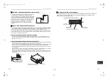
Procedure
3
Push
button to return to the usual display after
confirmation.
1. Check the check code according to the above
procedure.
2. Ask an authorized dealer or qualified service
(maintenance) professional to repair or maintain the
air conditioner.
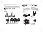
Check code
Indoor UNIT No. in which a
problem occurred
3
2
1
Check codes and parts to be checked
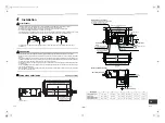
Check method
On the remote control (Wired remote control, Central control remote control) and the interface P.C. board of the
outdoor unit (I/F), a check display LCD (Remote control) or 7-segment display (on the outdoor interface P.C. board)
to display the operation is provided. Therefore the operation status can be known. With this self-diagnosis function,
a trouble or position with trouble of the air conditioner can be found as shown in the table below.
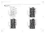
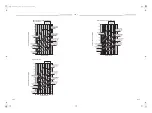
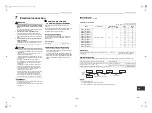
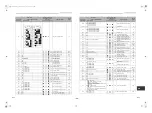
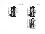
Check code list
The following list shows each check code. Find the check contents from the list according to part to be checked.
• To check from indoor remote control: See “Wired remote control display” in the list.
• To check from outdoor unit: See “Outdoor 7-segment display” in the list.
• To check from indoor unit with a wireless remote control: See “Sensor block display of receiving unit” in the list.
IPDU : Intelligent Power Drive Unit
: Lighting,
: Flashing,
: Goes off
ALT : Flashing is alternately when there are two flashing LED.
SIM : Simultaneous flashing when there are two flashing LED.
Check code
Wireless remote control
Check code name
Judging
device
Wired remote
control display
Outdoor 7-segment display
Sensor block display of
receiving unit
Auxiliary code
Operation Timer Ready Flash
E01
—
—
Communication trouble between indoor
and remote control
(Detected at remote control side)
Remote
control
E02
—
—
Remote control transmission trouble
Remote
control
E03
—
—
Communication trouble between indoor
and remote control (Detected at indoor
side)
Indoor
E04
—
—
Communication circuit trouble between
indoor / outdoor (Detected at indoor
side)
Indoor
E06
E06 No. of indoor units in which sensor has been normally
received
Decrease of No. of indoor units
I/F
—
E07
—
Communication circuit trouble between
indoor / outdoor (Detected at outdoor
side)
I/F
E08
E08 Duplicated indoor addresses
Duplicated indoor addresses
Indoor / I/F
E09
—
—
Duplicated header remote controls
Remote
control
E10
—
—
Communication trouble between indoor
MCU
Indoor
E12
E12 01: Indoor / Outdoor communication
02: Communication between outdoor units
Automatic address start trouble
I/F
E15
E15
—
Indoor is nothing during automatic
addressing
I/F
E16
E16 00: Capacity over
01 ~:No. of connected units
Capacity over / No. of connected indoor units
Combined capacity of indoor units
exceeds 120% of combined capacity of
outdoor units. (SMMS-i only)
I/F
E18
—
—
Communication trouble between indoor units
Indoor
E19
E19 00: Header is nothing
02: Two or more header units
Outdoor header units quantity trouble
I/F
E20
E20 01: Outdoor of other line connected
02: Indoor of other line connected
Other line connected during automatic
address
I/F
E23
E23
—
Sending trouble in communication
between outdoor units
I/F
E25
E25
—
Duplicated follower outdoor addresses
I/F
E26
E26 No. of outdoor units which received signal normally
Decrease of No. of connected outdoor units
I/F
E28
E28 Detected outdoor unit number
Follower outdoor unit trouble
I/F
37-EN
38-EN
+00EB99808801_01EN.book Page 19 Monday, April 11, 2016 2:30 PM


