background image

6. PRINTER OPERATION 

EO1-33032 

6.2 Installing the Printer Drivers 

6- 7 

6.2.3  Uninstalling the TEC  

B-492 Printer Driver 
(Cont.) 


5.

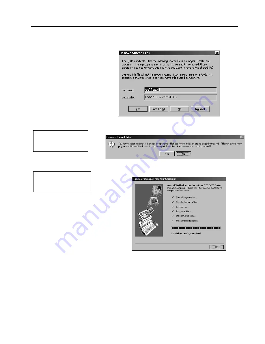
  When the following screen appears, click on the 

Yes To All

 button. 

If this screen does not appear, the screen of Step 

7

 will appear instead.   


6.

  Upon clicking on the 

Yes To All

 button, the following screen appears 

to confirm the deletion of shared file.  Click on the 

Yes

 button.   


7.

  Printer driver deletion starts.  When the deletion is completed, click on 

the 

OK

 button.  


NOTE: 

Deleting the shared files does 
not affect other programs.  

NOTE: 

Please note that it may take time 
to delete the printer driver.   

Содержание B-492L

Страница 1: ...TEC Barcode Printer B 492L R TH10 SERIES Owner s Manual ...

Страница 2: ...gebruiker ertoe kunnen dwingen sommige maatregelen te moeten treffen VERWITTIGING Questo è un prodotto in Classe A In un contesto domestico questo prodotto può causare interferenze radio per le quali l utente dovrebbe prendere le adeguate precauzioni ATTENZIONE This equipment has been tested and found to comply with the limits for a Class A digital device pursuant to Part 15 of the FCC Rules These...

Страница 3: ...lug with wet hands as this may cause electric shock If the machines share the same outlet with any other electrical appliances which consume large amounts of power the voltage will fluctuate widely each time these appliances operate Be sure to provide an exclusive outlet for the machine as this may cause fire or electric shock Do not place metal objects or water filled containers such as flower va...

Страница 4: ...ht high temperatures high humidity dust or gas Ensure the printer is operated on a level surface Any data stored in the memory of the printer could be lost during a printer fault Try to avoid using this equipment on the same power supply as high voltage equipment or equipment likely to cause mains interference Unplug the machine whenever you are working inside it or cleaning it Keep your work envi...

Страница 5: ... 5 2 6 1 Turning ON the Printer 2 5 2 6 2 Turning OFF the Printer 2 5 2 7 Loading the Media 2 6 2 8 Loading the Ribbon 2 11 2 9 Inserting the Optional PCMCIA Cards 2 12 2 10 Test Print 2 13 3 ON LINE MODE 3 1 3 1 Operation Panel 3 1 3 2 Operation 3 2 4 MAINTENANCE 4 1 4 1 Cleaning 4 1 4 1 1 Print Head Platen 4 1 4 1 2 Media Guide Plate Pinch Roller Sensors 4 2 4 1 3 Paper Holder 4 4 4 1 4 Covers a...

Страница 6: ...3 A4 5 Printer Parameter Fine Adjustment A4 6 A4 6 Test Print A4 14 A4 7 Dump Mode A4 20 A4 8 Additional Information A4 21 A4 8 1 Self Diagnostic Test Result Sample and Descriptions A4 21 A4 8 2 Maintenance Counter Parameter Check Print Sample and Descriptions A4 24 A4 8 3 Magnified Views of Slant Line Pattern A4 27 APPENDIX 5 PRINT SAMPLES A5 1 GLOSSARIES INDEX CAUTION 1 This manual may not be co...

Страница 7: ...es sec and 254 mm sec 10 inches sec Separation of the power supply unit realized a compact body of the printer When the optional interface board is installed Web functions such as remote maintenance and other advanced network functions are available The PCMCIA Interface Board and the KB 80 QM Keyboard Unit are provided as optional equipment Unpack the printer as per the Unpacking Instructions supp...

Страница 8: ...256 10 1 265 10 4 300 11 8 5 0 2 18 0 7 223 8 8 5 0 2 117 5 4 6 117 5 4 6 232 5 9 2 209 3 8 2 10 0 4 125 4 9 100 3 9 282 11 1 149 3 5 9 264 10 4 300 11 8 5x 5 5 117 5 4 6 117 5 4 6 223 8 8 18 0 7 5 0 2 256 10 1 265 10 4 5 0 2 300 11 8 100 3 9 149 3 5 9 264 10 4 300 11 8 282 11 1 232 5 9 2 209 3 8 2 10 0 4 125 4 9 Dimension mm inch ...

Страница 9: ...Type 1 5 3 Side View L Type R Type Top Cover Operation Panel Media Inlet Media Guide Supply Window Print Head DC Power Connector PCMCIA Card Slot 2 slots Keyboard Interface Connector Expansion I O Interface Connector Parallel Interface Connector Centronics Serial Interface Connector RS 232C ...

Страница 10: ...ration Panel Ribbon Stopper Ribbon Shaft Ribbon Shaft Holder Plate Pinch Roller Lever Head Lever Strip Roller Release Lever FEED RESTART PAUSE POWER ON LINE ERROR LCD Message Display FEED Key ERROR LED Red ON LINE LED Green POWER LED Green RESTART key PAUSE key NOTE The illustrations used hereafter are of the L type as the operating procedure is common to both L and R types ...

Страница 11: ...1 33032 1 6 Appearance of the Power Supply Unit 1 5 1 6 Appearance of the Power Supply Unit 1 6 1 Dimensions Dimensions mm inch 1 6 2 Front View 2000 78 7 265 10 4 10 0 4 76 3 0 170 6 7 DC Power Connector Power Switch Inlet ...

Страница 12: ...is unit to power it Do not operate the printer with the cover open Be careful not to allow fingers or articles of clothing to get caught into any of the moving parts of the printer Make sure to turn off the printer power and to remove the power cord from the printer whenever working on the inside of the printer or when cleaning the printer For best results and longer printer life use only TOSHIBA ...

Страница 13: ...on 2 8 9 Turn the Power ON Refer to Section 2 6 10 Set the threshold Refer to Section 5 4 11 Perform a test print Refer to Section 2 10 and Appendix 4 6 12 Install the Printer Drivers Refer to Section 6 When installing the printer it is important to ensure that the fan filter is attached before using the printer The fan filter consists of 2 parts 1 Filter Pad 2 Filter Retainer To fit the fan filte...

Страница 14: ... These are A serial cable connection between the printer s RS 232 serial connector and one of your host computer s COM ports Refer to APPENDIX 3 A parallel cable connection between the printer s standard parallel connector and your host computer s parallel port LPT An Ethernet connection using the optional PCMCIA interface board and LAN card Refer to section 2 9 The diagram below shows all the pos...

Страница 15: ... the other end of the power cord into a grounded outlet as shown in the figure below CAUTION 1 Make sure that the printer power switch is turned to the off position before connecting the power cord to prevent possible electric shock or damage to the printer 2 Use only the power cord supplied with the printer Use of any other cord may cause electric shock or fire 3 Connect the power cord to a suppl...

Страница 16: ...ch verify that the ON LINE message is on the LCD Message Display and that the ON LINE LED light is on and not flashing 2 To turn OFF the printer power press the power switch as shown in the diagram below Note that is the power OFF side of the switch CAUTION Use the power switch to turn the printer On Off Plugging or unplugging the power cord to turn the printer On Off may cause fire an electric sh...

Страница 17: ...ing etc being drawn into the moving parts be sure to load the media once the printer has stopped moving completely 2 To avoid injury be careful not to trap your fingers while opening or closing the cover 3 Be sure to open the top cover fully otherwise the top cover may close causing injury NOTES 1 When the head lever is turned to position d the print head is raised 2 When the pinch roller lever is...

Страница 18: ...6 Pass the media straight from the paper holders to paper outlet The media should be centred on the strip plate otherwise skew feeding or a paper jam may occur Check that the media is positioned so that the distances from the media edge to the end of the scale marked on the strip plate Distances A and B in the figure below are almost equal NOTE The media guide should be positioned so that the medi...

Страница 19: ...the black mark sensor position 1 Pull about 500 mm of media out of the front of the printer turn the media back on itself and feed it under the print head past the sensor so that the black mark can be seen from above 2 Turn the adjusting knob to move the black mark sensor so that it is in line with the center of the black mark on the media indicates the position of the black mark sensor NOTES 1 Tu...

Страница 20: ...Strip mode In strip mode as each label is printed the backing paper is automatically removed from the label at the strip plate 1 Set the ribbon shaft holder plate and turn the head lever and the pinch roller lever to position cto close 2 Remove enough labels from the leading edge of the media to leave 500 mm of backing paper free 3 Push the pinch roller release lever toward the front of the printe...

Страница 21: ...ch roller until it locks into position 6 If the loaded media is direct thermal media a chemically treated surface the media loading procedure is now complete Close the ribbon shaft holder plate and turn the head lever and the pinch roller lever to position cto close Then close the top cover If the media is a standard media it is also necessary to load a ribbon Refer to the following section 2 8 Lo...

Страница 22: ...y moving parts To reduce the risk of fingers jewellery clothing etc being drawn into the moving parts be sure to load the ribbon once the printer has stopped moving completely 2 To avoid injury be careful not to trap your fingers while opening or closing the cover 3 Be sure to open the top cover fully otherwise the top cover may close causing injury Ribbon Stopper Ribbon Ribbon Shafts Ribbon Senso...

Страница 23: ...ards such as LAN Cards 1 Make sure that the printer s power switch is in the OFF position 2 Hold the PCMCIA Card so that the side printed with the model name faces right Insert the card into the proper slot until the Eject Button pops out CAUTION 1 To protect PC cards discharge static electricity from your body by touching the metal cabinet of the printer before touching the card 2 Before insertin...

Страница 24: ...CC Maxell EF 4M TB DC Capacity 4MB Readable writable Centennial Technologies INC FL04M 15 11119 03 INTEL IMC004FLSA Simple TECHNOLOGY STI FL 4A Mitsubishi MF84M1 G7DAT01 PC Card KING MAX FJN 004M6R Flash Memory Card PC Card FJP 004M6R Capacity 4MB Read only A print test should be performed to check that the printer is operating correctly During this test the printer will first issue a blank page o...

Страница 25: ...6 characters can be displayed on this line There are three LED lights on the Operation Panel LED Illuminates when Flashes when POWER The printer is turned on ON LINE The printer is ready to print The printer is communicating with your computer ERROR Any error occurs on the printer There are three keys on the Operation Panel PAUSE Used to stop printing temporarily RESTART Used to restart printing F...

Страница 26: ...n error message appears The printer stops printing automatically The number on the right hand side shows the remaining number of labels to be printed 3 To clear the error press the RESTART key The printer resumes printing 4 If the PAUSE key is pressed during printing the printer stops printing temporarily The number on the right hand side shows the remaining number of labels to be printed 5 When t...

Страница 27: ...ightly moistened with ethyl alcohol or isopropyl alcohol WARNING 1 Be sure to turn OFF the power of the power supply unit before performing maintenance Failure to do this may cause an electric shock 2 To avoid injury be careful not to pinch your fingers while opening or closing the cover and print head block 3 Be careful when handling the print head as it becomes very hot immediately after printin...

Страница 28: ...2 Wipe the bottom of the media guide with a cloth moistened with alcohol WARNING NOTES 1 A print head cleaner or lapping sheet is not enclosed with the printer Please use a TEC approved print head cleaner or lapping sheet which can be purchased from an authorised TOSHIBA TEC service representative 2 Do not rub the print head element with a lapping sheet excessively or the print head life will be s...

Страница 29: ...h the pinch roller release lever toward the front of the printer to release the strip pinch roller unit 5 Wipe the feed roller and pinch rollers with a soft cloth moistened with alcohol 6 Remove dust or paper particles from the black mark and feed gap sensors using an air blower Locking Screw Paper Guide B Feed Roller Pinch Roller Strip Pinch Roller Strip Feed Roller ...

Страница 30: ...s 4 Wipe the paper holders upper and lower plates with a soft cloth moistened with alcohol Wipe the Cover and Operation Panel with a dry soft cloth Wipe off dirt with a soft cloth slightly moistened with water Locking Screw Set Screw Set Screw Paper Holders Upper Plate Paper Entry Guide Paper Holders Lower Plate Loose CAUTION Do not use any volatile solvents including thinner and benzene as this m...

Страница 31: ...y dust or gas The thermal paper used for direct thermal printing must not have specifications which exceed Ca2 K Na 800 ppm and Cl 600 ppm Some ink used on pre printed media may contain ingredients which shorten the print head s product life Do not use labels pre printed with ink which contain hard substances such as carbonic calcium CaCO3 and kaolin Al2O3 2SiO2 2H2O For further information please...

Страница 32: ...a being used Finally resend the print job 3 Adjust the sensor position Then press the RESTART key 4 Replace the loaded media with one that matches the programmed size then press the RESTART key or turn the printer off and then on select a programmed size that matches the loaded media Finally resend the print job 5 Refer to Section 6 4 to set the threshold If this does not solve the problem turn of...

Страница 33: ...his does not solve the problem turn off the printer again and call a TOSHIBA TEC authorized service representative 5 2 Possible Problems This section describes problems that may occur when using the printer and their causes and solutions Possible Problems Causes Solutions The printer will not turn on 1 The AC Power Cord or DC Power Cord is disconnected 2 The AC outlet is not functioning correctly ...

Страница 34: ... 2 Load the media 3 Press the PAUSE key 4 The printer enters the pause mode 5 Press and hold the PAUSE key for at least 3 seconds in the pause state 6 The sensor type is displayed 7 Select the sensor to be adjusted by pressing the FEED key CAUTION Do not use any tool that may damage the print head NOTES 1 If the PAUSE key is released within 3 seconds while in the pause state the paper will not fee...

Страница 35: ... key until more than 1 5 labels have been issued The media will continue to be fed until the PAUSE key is released Threshold setting for the selected sensor is completed by this operation 9 Press the RESTART key 10 The printer is in stand by 11 Send an issue command from the PC to the printer 3 86 21 1 21 1 ...

Страница 36: ...ough the printer by the paper feed mechanism the thermal head continuously prints the image as a series of dot lines at a resolution of 305 dots per inch horizontally and vertically Precision feeding and back feeding of the label stock is accomplished through the use of specialized stepping motors and photo sensors The label gap sensor or the black mark sensor tells the printer electronics when th...

Страница 37: ...en select and click on the Run 3 Type in D DRIVER SETUP EXE and click on the OK button D may be replaced with your CD drive s letter 4 The screen will change as shown below 5 After the Install Shield temporary files have been loaded the display will change to the Welcome screen as shown below NOTE Windows 3 1 is not supported Windows 3 1 Windows 95 Windows 98 Windows NT and Windows 2000 are regist...

Страница 38: ...ck on the Yes button If you do not accept the conditions click on the No button 8 Upon clicking on the Yes button the screen will change to list the available TEC driver sets For this printer select TEC B 492 and click on the Next button 9 The screen will change to the following When the printer is directly connected to this PC select Local Printer otherwise select Network Printer Then click on th...

Страница 39: ...n you selected the Network Printer in Step 9 enter a network path and click on the Next button If the network path is unknown click on the Browse button and select the same printer that you chose in Step 8 12 The screen will show the selected printer name Change the printer name if necessary NOTE Be sure to select the same printer that you are going to install NOTE If you specify the same name as ...

Страница 40: ... driver files copy will start 14 After all of the files have been transferred the display will change to the Setup Complete screen Select Yes I want to restart my computer now then click on the Finish button 15 After the TEC Printer Driver has been successfully loaded the Printers screen should appear as shown below showing the TEC B 492 as being successfully installed ...

Страница 41: ...con 2 Select TEC B 492 Printer and click on the Add Remove button 3 When the following screen appears click on the Yes button 4 When the Registration information deletion screen appears click on the Yes button if you desire to delete the paper information If you do not desire to delete the information click on No button If this message does not appear go to the next step NOTES If the registration ...

Страница 42: ...does not appear the screen of Step 7 will appear instead 6 Upon clicking on the Yes To All button the following screen appears to confirm the deletion of shared file Click on the Yes button 7 Printer driver deletion starts When the deletion is completed click on the OK button NOTE Deleting the shared files does not affect other programs NOTE Please note that it may take time to delete the printer ...

Страница 43: ...1 6 mm sec 4 sec 127 mm sec 5 sec 203 2 mm sec 8 sec 20 mm to 112 mm 0 8 to 4 4 104 0 0 2 mm 4 1 B 492L for a left flow line B 492R for a right flow line 16 characters line 329 mm 245 mm 300 mm 13 0 9 6 11 8 Depth of the PCB block 125 mm 4 9 13 kg 28 7 lb Excluding Media and ribbon JAN8 JAN13 EAN8 EAN8 2 digits EAN8 5 digits EAN13 EAN13 2 digits EAN13 5 digits UPC E UPC E 2 digits UPC E 5 digits U...

Страница 44: ...e NOTE A1 3 Media Please make sure that the media to be used is approved by TOSHIBA TEC The warranties do not apply to problems caused by using media that is not approved by TOSHIBA TEC For information regarding TOSHIBA TEC approved media please contact a TOSHIBA TEC authorized service representative A1 3 1 Media Type This thermal transfer direct thermal printer is specifically designed for label ...

Страница 45: ...r 7K white or equivalent should be used Also the light transmission rate of the backing paper should be 22 or above 3 When perforating the media it should be done from the print side to the reverse side 4 Ink used for pre printing the media should not contain hard substances such as carbonic calcium CaCO3 and Kaolin Al2O3 2SiO2 2H2O 5 The reflectance of the black mark should be 10 or less when the...

Страница 46: ...or is movable within this range NOTES 1 Avoid printing in the area 1 5 mm wide from the media edges shaded area in the above figure 2 The center of media is positioned at the center of the print heads 3 Print quality is not guaranteed within 3 mm from the print head stop position including 1 mm slowup 4 Average print black rate should be 15 or less For bar code print area the print rate should be ...

Страница 47: ... Width 41 112 mm 1 6 to 4 4 41 68 84 and 112 mm 1 6 2 7 3 3 4 4 are recommended Length 600 10 0 m Max Outside Diameter φ90 mm φ3 5 Max NOTES 1 To ensure print quality and print head life use only TOSHIBA TEC specified ribbons 2 To avoid ribbon wrinkles use a ribbon which is the correct width for each media width used It is possible to use narrower ribbons than media width however the effective pri...

Страница 48: ...ed during feed Yes Yes 6 12 3 3 5 z The media has run out or the media is not loaded correctly Yes Yes 7 5 21 5525 z The ribbon has run out or has snapped A problem has occurred with the sensor that determines the torque for the ribbon motor Yes Yes 8 23 1 z Feeding or printing was attempted with the print head block open Yes Yes 9 29 5 23 1 z Feeding or printing was attempted with the top cover o...

Страница 49: ... However LF and NUL will not be displayed Example 1 ESC PC001 0A00 0300 2 2 A 00 B LF NUL Corrupt data The following message appears Example 2 ESC XR 0200 0300 0450 1200 1 LF NUL Command error The following message appears Example 3 ESC T20E 30 LF NUL Corrupt data The following message appears The character 3FH is displayed for character codes outside the ranges 20H to 7FH and A0H to DFH 3 5 7 ...

Страница 50: ...C Cable description The serial data cable used to connect the printer to a host computer should be one of the following two types NOTE Use an RS 232C cable with inch type securing screws on the connector DB 9S Connector to PC Pin No Signal 1 N C 2 RXD 3 TXD 4 DTR 5 GND 6 DSR 7 RTS 8 CTS 9 N C Housing Shield DB 9P Connector to Printer Pin No Signal 1 N C 2 TXD 3 RXD 4 DSR 5 SG 6 DTR 7 CTS 8 RTS 9 N...

Страница 51: ...rs on the printer In System Mode the FEED RESTART and PAUSE keys function as described below FEED Used to navigate the parameter mode or to fine adjust the parameters in the negative direction Down RESTART Used to release the printer from Pause condition to navigate the parameter mode or to fine adjust the parameters in the positive direction Up By pressing and holding the RESTART key in Pause con...

Страница 52: ...the Printer Parameter Fine Adjustment menu This leads to the Test Print menu This will Reset the printer RESTART RESTART RESTART RESTART 9 867 6 7 7 67 35 17 IMPORTANT The following menus are for Service Personnel only 2 PARAMETER SET 5 SENSOR ADJ 6 RAM CLEAR 7 IP ADDRESS Please do not change the settings for these items as doing so may cause the printer to malfunction If you should accidentally e...

Страница 53: ... 1 3 86 5 6 7 21 1 NOTE If the RESTART key is held for less than 3 seconds when the printer is in an error or pause state the printer will restart printing However when a communication error or command error occurs the printer will return to an idle condition PAUSE PAUSE FEED FEED RESTART RESTART FEED Select the ribbon type Print out the Maintenance Counter and Parameter Settings Perform a Self Di...

Страница 54: ...t out After the Maintenance Counter and Parameter Settings print out has been completed the display returns to 1 DIAG Vx x Press the PAUSE key twice then FEED key once The Self Diagnostic Test is ready Press the PAUSE key to start The printer starts the Self Diagnostic Test and prints out the result After printing is completed the display returns to 1 DIAG Vx x 5 6 7 5 21 75 16 0 17 1 1 217 1 35 1...

Страница 55: ...rt The printer starts checking the print head If there is no problem with the print head the print head check is complete Press the PAUSE key to return to 1 DIAG Vx x If there is a problem with the print head the following message is displayed Press the PAUSE key to return to 1 DIAG Vx x 1 1250 1 5525 NOTES 1 Make sure that the Top Cover is closed before starting the print head check 2 If HEAD ERR...

Страница 56: ...ransfer Print Tone Fine Adjustment Direct Thermal Ribbon Motor Drive Voltage Fine Adjustment Rewind Motor Ribbon Motor Drive Voltage Fine Adjustment Feed Motor Threshold Fine Adjustment Black Mark Sensor Threshold Fine Adjustment Feed Gap Sensor Outline of Printer Parameter Fine Adjustment In the Printer Parameter Fine Adjustment mode Fine adjustments can be made for each parameter like Print tone...

Страница 57: ...e fine adjustment press the PAUSE key NOTES 1 If the FEED and RESTART keys are pressed at the same time in the parameter setting the message returns to 3 ADJUST SET 2 If holding the FEED or RESTART key for 0 5 seconds or longer in the Printer Parameter Fine Adjustment the key will auto repeat 3 A changed parameter becomes enabled by pressing the PAUSE key 4 Use the FEED or the RESTART key to chang...

Страница 58: ... In strip issue the media feed should be stopped where a 1 mm length of label remains on the strip plate If however the feed stop position is improper due to too long gap length etc a fine adjustment should be performed 2 The fine adjustment value equals the sum of the fine adjustment values set by the PC command and this parameter The maximum strip position fine adjustment value is 50 0mm When th...

Страница 59: ...nge down to 9 5 mm RESTART key Pressing the RESTART key once causes a 0 5mm change up to 9 5 mm After completing the fine adjustment press the PAUSE key NOTE The fine adjustment value equals the sum of the fine adjustment values set by the PC command and this parameter The maximum back feed length fine adjustment value is 9 5mm When the addition of the values reaches the maximum the value remains ...

Страница 60: ... PP 867 PP 867 PP 867 PP NOTES 1 The X Axis fine adjustment is performed to fine adjust the print position in horizontal direction left or right 2 Adjust the X axis within the effective print range when the value reaches the coordinate 0 the value remains unchanged even if the subsequent negative fine adjustments are made 3 This adjustment cannot be used in the Self Test mode or Test print 4 The f...

Страница 61: ...ange up to 10 tones After completing the fine adjustment press the PAUSE key NOTES 1 The fine adjustment value equals the sum of the fine adjustment values set by the PC command and this parameter The maximum print tone fine adjustment value is 10 The following table shows the maximum fine adjustment value for each print speed Even if the set value exceeds the maximum value it will be automaticall...

Страница 62: ...completing the fine adjustment press the PAUSE key NOTES 1 The fine adjustment value equals the sum of the fine adjustment values set by the PC command and this parameter The maximum ribbon motor voltage fine adjustment value is 15 When the addition of values reaches the maximum the value remains unchanged even if subsequent fine adjustments are made 2 Each step corresponds to 5 of the standard vo...

Страница 63: ...motor With 3 ADJUST SET displayed press the PAUSE key 10 times to enter the Strip Motor Driving Speed Fine Adjustment menu After completing the fine adjustment press the PAUSE key NOTE This is useful to fine adjust the threshold if problems with media issue persist after the sensor threshold setting is performed See Section 6 4 Threshold Setting If the problem cannot be resolved please contact you...

Страница 64: ...rinters operation or for testing the quality of new ribbon or media RESTART FEED RESTART FEED RESTART FEED RESTART FEED RESTART FEED RESTART FEED RESTART FEED RESTART FEED RESTART FEED PAUSE PAUSE PAUSE PAUSE PAUSE PAUSE PAUSE PAUSE PAUSE 668 2817 35 17 63 V 6 1625 75 16 5 21 75 16 7 3 6 1250 1 PP 3 3 5 7 67 35 17 35 17 21 7 21 6 17 1 27 6 17 1 27 5 7 56 5 2 121 35 17 1 725 7 67 872 35 17 75 1 872...

Страница 65: ...the Print Condition for the Test Print The print conditions for Test Printing should be specified before printing When 4 TEST PRINT appears press the PAUSE key Issue Count Setting To enter the Issue Count Setting menu press the PAUSE key After selecting the issue count press the PAUSE key to go to Print Speed Setting 35 17 21 7 21 RESTART FEED 668 2817 668 2817 668 2817 668 2817 668 2817 668 2817 ...

Страница 66: ... printing mode press the PAUSE key to go to Issue Mode Selection 35 17 63 V 35 17 63 V 35 17 63 V RESTART FEED 6 1625 121 6 1625 5 7 RESTART FEED 6 1625 75 16 5 21 12 5 21 5 21 75 16 RESTART FEED 5 21 75 16 No ribbon Transmissive ribbon None Black Mark Sensor 6 1625 75 16 Feed Gap Sensor NOTE Select the sensor type which matches the media being used Basically the Reflective Sensor Black Mark Senso...

Страница 67: ...r Feed Selection Select whether or not a paper feed is performed After selecting the paper feed press the PAUSE key If PAPER FEED was selected the printer will feed the media The display returns to the 4 TEST PRINT 7 3 6 1250 7 3 3 2 7 3 6 1250 RESTART FEED Batch mode Strip mode RESTART FEED 1 PP 1 PP 1 PP 3 3 5 3 3 5 12 3 3 5 RESTART FEED Paper feed is available Paper feed is not available NOTE P...

Страница 68: ...sing the PAUSE key causes the display to show SLANT LINE 1DOT again Then press the FEED key Slant Line 3 dots While displaying the Slant Line 3 dots press the PAUSE key to start printing the slant line patterns 3 dots After printing is completed the display returns to 4 TEST PRINT Pressing the PAUSE key causes the display to show SLANT LINE 3DOT again Then press the FEED key 35 17 21 7 21 6 17 1 2...

Страница 69: ...splay returns to 4 TEST PRINT Pressing the PAUSE key causes the display to show NON PRINTING again Then press the FEED key Factory Test While displaying the Factory test press the PAUSE key to start printing the factory test pattern After printing is completed the display returns to 4 TEST PRINT Pressing the PAUSE key causes the display to indicate FACTORY TEST again Then press the FEED key 5 7 56...

Страница 70: ...E key again causes the printer to print characters on 5 pieces of media In Dump mode any characters sent from the host computer will be printed Received characters are expressed in hexadecimal values This allows the user to verify programming commands and debug their program And for other details please refer to your nearest TOSHIBA TEC service representative NOTE Select AUTO PRINT TRAN when using...

Страница 71: ...LAN SENSOR H 20 C A 22 C S 25 C R 4 2V T 2 5V RANK 7 DIP SW 1 ON 2 OFF 3 OFF EXP I O NG KEY BRD NG NOTES 1 Print conditions Preset count 1 Print speed 5 sec Sensor No sensor Printing method Thermal transfer Supply length 59 mm Issue mode Batch printing 2 Software version No Part No of ROM and checksum will vary with the software version of PROGRAM ROM 3 The last two digits of the checksum are usua...

Страница 72: ...A 22 C S 25 C R 4 2V T 2 5V RANK 7 Checksum of Font area Font area OK Data in the check area can be properly read written NG Data in the check area cannot be properly read written EEPROM Backup Memory Capacity of DRAM System Drawing memory ATA ATA Card is inserted LAN LAN card is inserted FSH Flash memory card is inserted NO Unformatted ATA card Flash memory card or no card is inserted Slot PCMCIA...

Страница 73: ... ON 2 OFF 3 OFF 9 Expansion I O Interface Check EXP I O OK 10 DIN Connector for the Keyboard KB 80 Check KEY BRD OK Loopback test OK The circuit has no problem NG The circuit has a problem or loopback jig is not attached Expansion I O PC board OK The connector has no problem NG The connector has a problem or loopback jig is not attached DIN Connector for the KB 80 keyboard Connector FCN 781P024 G ...

Страница 74: ... 0V THRESHOLD T 1 4V FONT PC 850 0 CODE AUTO RIBBON TRANS SPEED 9600 DATA LENG 8 PARITY EVEN CONTROL XON READY AUTO MESSAGE ENGLISH RIBBON SAVE ON FEED KEY FEED EURO CODE B0 AUTO HD CHK OFF ACK BUSY TYPE1 WEB PRINTER OFF KB80 CONNECT OFF RIBBON NEAR END 30m PRTR IP ADDRESS 192 168 010 020 GATE IP ADDRESS 000 000 000 000 SUBNET MASK 255 255 255 000 TTF AREA 704kB EXT CHR AREA 128kB PC SAVE AREA 64k...

Страница 75: ...wer failure count Counts the number of times the power restores while the CPU is busy after reset 0 to 15 times Descriptions of the Parameters No Item Contents 10 Feed length fine adjustment PC KEY 50 0 mm to 50 0 mm 11 Strip position fine adjustment PC KEY 50 0 mm to 50 0 mm 12 Back feed length fine adjustment PC KEY 9 9 mm to 9 9 mm 13 Print tone fine adjustment Thermal transfer PC KEY 10 step t...

Страница 76: ...ibbon type NO RIBBON No ribbon TRANS Transparent ribbon end NON TRANS Opaque ribbon end 24 Baud rate 2400 2400 bps 9600 9600 bps 4800 4800 bps 19200 19200 bps 38400 38400 bps 25 Data length 7 7 bits 8 8 bits 26 Parity NON None ODD ODD EVEN EVEN 27 Transmission control code XON XOFF XON XOFF READY BUSY READY BUSY DTR XON READY AUTO XON XOFF READY BUSY DTR XON XOFF AUTO XON XOFF READY BUSY RTS RTS 2...

Страница 77: ... detection 30m Warning when the remaining ribbon length is about 30 m 70m Warning when the remaining ribbon length is about 70 m 37 Printer IP address 38 Gateway IP address 39 Subnet mask 40 True type font registration area size 0 KB to 896 KB unit of 64 KB 41 External character registration area size 0 KB to 896 KB units of 64 KB 42 PC saving area size 0 KB to 896 KB units of 64 KB 43 Socket comm...

Страница 78: ...APPENDIX 5 PRINT SAMPLES EO1 33032 APPENDIX 5 PRINT SAMPLES A5 1 APPENDIX 5 PRINT SAMPLES Font ...

Страница 79: ...2 APPENDIX 5 PRINT SAMPLES Cont Bar codes 0 JAN8 EAN8 1 MSI 2 Interleaved 2 of 5 3 CODE39 Standard 4 NW7 5 JAN13 EAN13 6 UPC E 7 EAN13 2 digits 8 EAN13 5 digits A CODE128 B CODE39 Full ASCII C CODE93 G UPC E 2 digits H UPC E 5 digits I EAN8 2 digits J EAN8 5 digits ...

Страница 80: ...ES A5 3 APPENDIX 5 PRINT SAMPLES Cont K UPC A L UPC A 2 digits M UPC A 5 digits N UCC EAN128 O Industrial 2 of 5 P PDF417 Q Data Matrix R Customer bar code S Customer bar code of high priority T QR code U POSTNET V RM4SCC W KIX Code X Micro PDF417 Z MaxiCode ...

Страница 81: ... set of alphanumeric characters in one style of type E g Helvetica Courier Times Gap Distance from the bottom of one label to the top of the next IPS Inchs per second A unit used to express print speed KB 80 keyboard interface This interface allows the B 492L R printer to connect to the optional KB 80 keyboard providing it with a standalone capability Label programs may be stored in the KB 80 flas...

Страница 82: ...o the media Supply Media and ribbon Thermal direct printing A printing method using no ribbon but thermal media which reacts to heat The thermal print head heats the thermal media directly causing print image to be printed on the media Thermal print head A print head using thermal transfer or thermal direct printing method Thermal transfer printing A printing method that uses the thermal print hea...

Страница 83: ...2 6 I Interface A1 1 Issue mode 2 9 A4 17 J Jammed media 5 1 5 3 K KB 80 QM keyboard 1 1 2 3 Keyboard interface 1 3 2 3 A1 1 Keyboard module A1 2 L Label A1 2 Label length A1 3 Label pitch A1 3 Label width A1 3 LCD message display 1 4 3 1 A1 1 M Maintenance counter A4 24 Media 4 5 A1 2 Media guide plate 4 2 O ONLINE LED 1 4 3 1 Operation Panel 1 3 1 4 3 1 P Parallel interface 1 3 2 3 A1 1 Parallel...

Страница 84: ...dth A1 5 Rotation A1 1 RS 232C 1 3 2 2 2 3 A1 1 A3 1 S Self diagnostic test A4 2 A4 3 A4 21 Sensor 2 8 5 1 Serial interface 1 3 2 3 A1 1 A3 1 Supply voltage A1 1 T Test print 2 13 A4 14 Thermal direct A1 1 Thermal transfer A1 1 Threshold setting 5 3 Transmissive sensor A1 3 Two dimensional code A1 1 W Weight A1 1 ...

Страница 85: ......

Страница 86: ...E PRINTED IN JAPAN EO1 33032 ...

Отзывы: