


- 7 -
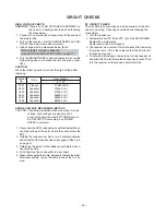
R, G, B FOCUS ADJUSTMENT
1. Before adjusting the R, G, B FOCUS, remove the 4 screws
of Lens Assembly which is fixed on the CRT Assembly.
(See page 4.)
Then turn around the Lens Assembly by 180 to adjust
the fastening screw (Fig. a) and fasten the 4 screws to
secure Lens Assembly.
2. Select the adjustment mode. (See page 10.)
3. Press “7” button to display the built-in cross-hatch.
4. Press “0” and “RTN” buttons to make the picture a single
Red color.
100 button ................ to erase Red color
0 button .................... to erase Green color
RTN button .............. to erase Blue color.
5. Loosen the fasten screw and adjust Red lens focus to best
focusing point of picture center. Then fasten the screw.
(See Fig. a.)
Fig. a
6. Adjust FOCUS VR “R” of FOCUS PACK to find best fo-
cusing point of picture center.
7. Repeat steps 3 to 5 for Green and Blue colors.
TILT ADJUSTMENT
Rotate R, G, B deflection yoke so that picture becomes hori-
zon, then fasten screw.
CENTERING ADJUSTMENT
1. Stretch a thread between two center of screen edge (top
and bottom, left and right).
2. Receive NTSC.
Then select SERVICE MODE. (See Page 10.)
3. Select CONVERGENCE ADJUSTING mode, and press
"7" button to display the internal net pattern.
Move Cursol and recognize horizontal line indicated Y:4.
This line is vertical center. Push "9" button to display the
vertical stripes, and recognaize horizontal center.
4. Perform VCEN adjustment. (See page 17.)
5. Adjust G centering magnet so that the cross-bar pattern
center comes to screen center.
6. Perform HEIGHT adjustment .
7. Perform VERT. LINEARITY adjustment.
8. Perform WIDTH adjustment. (See page 17.)
9. Check whole quality of green line.
10. Adjust R, B centering magnet so that the cross-bar pat-
tern center comes to screen center.
Содержание 51HX84
Страница 1: ...SERVICE MANUAL Projection Television 51HX84 57HX84 N4PS Chassis FILE NO 020 200410 ...
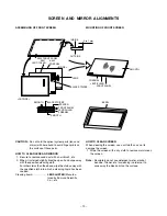
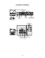
Страница 8: ... 8 LOCATION OF SCREEN AND FOCUS VR S FOCUS COVER Speaker grille G B R SCREEN ...
Страница 35: ...SCAN CONVERTER MODUL MHSU11 PD1738 U001 BOTTOM FOIL SIDE 36 37 ...
Страница 36: ...SCAN CONVERTER MODUL MHSU11 PD1738 U001 TOP COMPONENT SIDE 38 39 ...
Страница 44: ... 51 52 CIRCUIT BLOCK DIAGRAM ...
Страница 46: ...TOSHIBA CORPORATION 1 1 SHIBAURA 1 CHOME MINATO KU TOKYO 105 8001 JAPAN ...