background image

TD - Series

- 5 -

TD Series

Digital Solid State Soft Starter 48 - 1250A

2.5    Mounting and Cleaning

When drilling or punching holes in the enclosure, cover the electrical assembly
to prevent metal filings from becoming lodged in areas which can cause
clearance reduction or actually short out electronics. After work is complete,
thoroughly clean the area and reinspect the unit for foreign material. Make
sure there is sufficient clearance (six inches) all around the unit for cooling,
wiring and maintenance purposes. To maximize effective air flow and cooling,
the unit must be installed with its heat sink ribs oriented vertically and running
parallel to the mounting surface.

Remove all sources of power before cleaning the unit.

In dirty or contaminated atmospheres the unit should be cleaned on a regular
basis to ensure proper cooling. Do not use any chemicals to clean the unit.
To remove surface dust use 80 to 100 psi, clean, dry compressed air only. A
three inch, high quality, dry paint brush is helpful to loosen up the dust prior
to using compressed air on the unit.

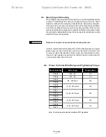
2.6    Power Terminal Wire Range and Tightening Torque

Note:  All wiring must be sized according to NEC standards.

    WARNING

Model Number

Wire range

Torque lbs/in

TD005

#18 - #4

20

TD006

#14 - #2

50

TD007

TD008

TD009

TD010

TD011

TD012

TD013

TD014

TD015

TD016

TD017

#6 - 250 kcmil

325

375

(3) #2 - 600 kcmil

375

(2) #2 - 600 kcmil

375

(2) #2 - 600 kcmil

(4) #2 - 600 kcmil

375

Содержание 48-1250 A

Страница 1: ...INSTRUCTION MANUAL TD SERIES Low Voltage Digital Solid State Starter 48 1250 A Issued 9 03 Manufactured in the USA INSTALLATION OPERATION MAINTENANCE DOCUMENT NBZ0001 ...

Страница 2: ......

Страница 3: ...irections that are contained in this Instruction Manual Use only Toshiba authorized replacement parts This equipment is designed and built in accordance with applicable safety standards in effect on the date of manufacture Unauthorized modifications can result in voiding the warranty severe injury death and property damage Do not make any modifications to this equipment without the written approva...

Страница 4: ...ty sign DANGER QUALIFIED OPERATORS ONLY Only qualified persons are to install operate or service this equipment according to all applicable codes and established safety practices A qualified person must 1 Carefully read the entire instruction manual 2 Be skilled in the installation construction or operation of the equipment and aware of the hazards involved 3 Be trained and authorized to safely en...

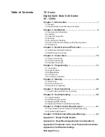
Страница 5: ...ntroduction 5 2 Digital Interface 5 3 Display Modes 5 4 Function List 5 5 Function Descriptions Chapter 6 Start Up 32 6 1 Quick Start 6 2 Start up Check List 6 3 Sequence of Operation Chapter 7 Fault Conditions 35 7 1 Fault Codes and Numbers In History Chapter 8 Troubleshooting 36 8 1 Failure Analysis 8 2 SCR Testing Procedure 8 3 Replacing SCR Devices 8 4 Replacing Printed Circuit Board Assembly ...

Страница 6: ......

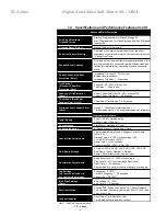
Страница 7: ...tory wired for 120 VAC control voltage and two or three wire start stop control Units can also be ordered with 240 VAC control voltage if required Programmable auxiliary contacts and provisions for interlocking are also included Chapter 1 Introduction 1 2 Specifications and Performance Features Type of Load Three phase AC induction motor AC Supply Voltage 208 600VAC 10 50 60 Hz HP Ratings 48 1250 ...

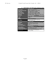
Страница 8: ...Time Range 1 60 minutes Starts per hour Lockout Timer Note 1 Range 1 10 successful starts per hour Time between starts 1 60 minutes between start attempts Type Rating Form C SPST Rated 5 amps 240 VAC max 1200 VA Run Indication Start Stop or Start End of Decel At Speed Indication At Speed Stop or At Speed End of Decel Acceleration Adjustments Programmable Ramp Types Voltage or Current Ramp VR or CR...

Страница 9: ...te Stamps Protocol Modbus RTU Signal RS 485 Network Up to 247 devices per mode Functionality Full operation status view and programming via communications port LED Readout 4 digit alpha numeric high brightness 7 segment display Keypad 8 functions keys with tactile feedback Status Indicators 8 LEDs Remote Mount Capability Up to 10 feet 3 meters from chassis Operating Memory DRAM loaded from EPROM a...

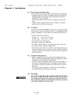
Страница 10: ...st and corrosive gas Free from excessive vibration below 0 5G Open panel units must be mounted in the appropriate type of enclosure Enclosure size and type must be suitable to dissipate heat generated by the soft starter Contact factory for assistance in sizing enclosures 2 3 Initial Unit Inspection Make a complete visual check of the unit for damage which may haveoccurredduringshippingandhandling...

Страница 11: ...riented vertically and running parallel to the mounting surface Remove all sources of power before cleaning the unit Indirtyorcontaminatedatmospherestheunitshouldbecleanedonaregular basis to ensure proper cooling Do not use any chemicals to clean the unit To remove surface dust use 80 to 100 psi clean dry compressed air only A three inch high quality dry paint brush is helpful to loosen up the dus...

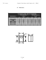
Страница 12: ... Overall Dimensions Mounting Dimensions Model Number inches inches A B C D E F TD005A TD007A 16 5 10 10 15 9 9 0 28 TD008A 20 20 1 12 18 5 17 5 0 44 TD009A TD010A 27 20 1 11 2 25 5 17 5 0 44 TD011A TD013A 29 5 20 1 11 5 25 5 17 5 0 44 TD014A TD015A 45 33 12 8 43 3 31 3 0 44 TD016A TD017A 33 33 15 2 31 2 31 2 0 44 ...

Страница 13: ... F001 to enter motor FLA as indicated on the motor nameplate Do not calculate for service factor this is programmed separately in F002 Note If F001 is left at the factory default the unit will not operate If the user attempts to start the TD without entering the motor nameplate FLA into this Function the TD will Fault and the display will read nFLA for no Full Load Amps 3 1 3 Disabling the Overloa...

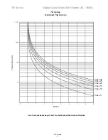
Страница 14: ...urve options 5 10 15 20 25 and30 Programtheappropriatecurveaccordingtothecharacteristics of your motor and load NEMA Class trip curves are based on a common tripping point of 600 of rated current Curves vary by the amount of time before the unit trips As an example a Class 20 curve will trip in 20 seconds at 600 The factory default setting of Class 10 will trip in 10 seconds at 600 3 2 1 Dual Over...

Страница 15: ...s Digital Solid State Soft Starter 48 1250A Note FactorydefaultsettingisClass10 forbothStartandRunOverloadProtection Class 30 Class 25 Class 20 Class 15 Class 10 Class 5 MFLA Time in Seconds TD Series Overload Trip Curves ...

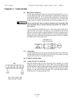
Страница 16: ...motor or load connected to the unit In areas where lightning is a significant problem stationary air gap lightning arrestors should be considered and utilized on the input power source TD Series Unit Power Connections 4 1 1 Grounding Connect the ground cable to the ground terminal as labeled on the unit Refer to the National Electrical Code for the proper ground wire sizing and be sure that the gr...

Страница 17: ...and then cools off When two wire connection method is used the user s control circuit must be interlocked to prevent automatic restart when protective devices reset Refer to section 3 1 3 b 4 2 4 Relay Contacts All the relay contacts are FORM C common N O N C except the optical triac output TOSHIBA recommends fusing all contacts with external fuses TB2 is the terminal block for all auxiliary conta...

Страница 18: ...conveyor belt The characteristics for starting an unloaded conveyor can be programmed for ramp 1 The characteristics for starting a loaded conveyor can be programmed for ramp 2 4 3 Interlock Connection TB1 provides a connection point for an external user N C normally closed interlock device between pins 2 and 3 Examples of the use of this interlock connection would be for conditions such as low oi...

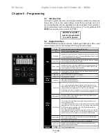
Страница 19: ...hange function number or value Read Enter Selects and stores the value of a function Power On Control power is present At Speed Motor is at full speed and power The SCRs have phased fully on Shorted SCR Shorted SCR has been detected in the unit Refer to section 8 2 for instructions on checking SCRs Phase Loss One or more of the phase currents is low or has been lost while the motor was starting or...

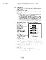
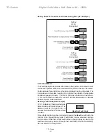
Страница 20: ...arrow 0121 Indicates that Phase B is drawing 121 amps Press the UP arrow NOTE Decimal points are not present in the readouts for Phase B and Phase C 0120 Indicates that Phase C is drawing 120 amps Press the UP arrow H051 Indicates that the motor has 51 of its thermal capacity remaining 5 3 2 Program Mode Use the Program Mode to view or change Function Fn settings To enter the Program Mode press th...

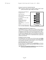
Страница 21: ...display of a customer password is encrypted If you do not have a record of the password and need to gain access contact TOSHIBA Tech Support Be ready to provide the TD Series serial number and the four digits in the encrypted display If the display reads Err when the READ ENTER key is pressed the parameter lock is enabled Changing a Function s Set Value Use the UP arrow key to increment the value ...

Страница 22: ...cter can be eitherA C or D to denote when the fault occurred A denotes Acceleration C denotes Constant speed D denotes Decel Reading Fault Code See Example PLC IndicatesaPhaseLossfaultwas detected while at Constant Speed The decimal point to the right of the C denotes that this is the most recent fault condition Once a fault condition has been corrected pressing the Reset key will return the reado...

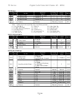
Страница 23: ...o 2 Disabled Overload 1 0 Manual 5 5 1 5 5 1 F006 F009 Reserved Reserved Reserved Reserved Motor and Overload Fn Group Function Adjustment Range Setting Increments Factory Setting Section F010 Ramp Select VR Voltage Ramp CR Current Ramp Range is 1 4 Setting to 1 Ramp 1 VR Ramp 2 VR Setting to 2 Ramp 1 CR Ramp 2 CR Setting to 3 Ramp 1 VR Ramp 2 CR Setting to 4 Ramp 1 CR Ramp 2 VR 1 1 VR1 VR2 5 5 2 ...

Страница 24: ...elay 1 20 seconds 1 second 1 second 5 5 6 F036 Under Current Trip 0 Disabled 1 Enabled 1 0 Disabled 5 5 6 F037 Under Current Trip 10 90 note1 1 40 5 5 6 F038 Under Current Trip Delay 1 60 seconds 1 second 2 seconds 5 5 6 F039 Coast Down Lockout Timer 0 Disabled 1 Enabled 1 0 Disabled 5 5 6 F040 Coast Down Lockout Time 1 60 minutes 1 minute 5 minutes 5 5 6 F041 Starts per Hour Lockout 0 Disabled 1 ...

Страница 25: ...ys Fn Group Function Adjustment Range Setting Increments Factory Setting Section F055 Communications 0 Disabled 1 Enabled 1 0 5 5 8 F056 Baud Rate 9 6 38 4 KB 9 6 KB 9 6 KB 5 5 8 F057 Modbus Address 1 247 1 1 5 5 8 Reserved Reserved Reserved Reserved 5 5 8 F058 F059 Communications Fn Group Function Adjustment Range Setting Increments Factory Setting Section F060 Parameter Lock User Password Range ...

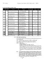
Страница 26: ...mmableintoF001will be limited to 85 of the starter Max Amp rating 100 15 Fn Group Function Adjustment Range Setting Increments Factory Setting Section F075 Fault History 1 Latest Fault 0 1 27 Fault see Fault code list 0 No fault history View Only 0 5 5 10 F076 Time Stamp Fault 1 00 00 23 59 hh mm hh 00 23 mm 00 59 View Only 00 00 EST 5 5 10 F077 Date Stamp Fault 1 01 01 12 31 MM DD MM 01 12 DD 01 ...

Страница 27: ...2 for details on trip curves F004 Overload Class During Run Factory Setting 10 Class 10 Range 5 30 NEMA UL Class Set value according to the instructions provided by your motor equipment manufacturer This trip curve will not be enabled until the motor has reached full speed F005 Overload Reset Factory Setting 0 Manual Range 0 2 Set value to determine starter behavior after an overload condition has...

Страница 28: ...nce to Ramp 2 Select Voltage Ramp by setting F010 1 factory default When Voltage Ramp is selected Set Initial Torque with F011 see below Set Ramp with F013 see below Set Maximum Current Limit with F014 see below Or Select Current Ramp by setting F010 2 When Current Ramp is selected Set Initial Torque with F012 see below Set Ramp Time with F013 see below Set Maximum Current Limit with F014 see belo...

Отзывы: