background image

– 2 –

TABLE  OF  CONTENTS

SERVICE SAFETY PRECAUTIONS .................................................................................................................................... 3

HANDLING THE LCD MODULE .......................................................................................................................................... 5

SERVICE MODE .................................................................................................................................................................. 7

LOCATION OF CONTROLS ............................................................................................................................................... 12

LAYOUT OF MAJOR BOARDS .......................................................................................................................................... 14

MECHANICAL DISASSEMBLY .......................................................................................................................................... 15

EXPLODED VIEWS ............................................................................................................................................................ 17

PACKING DISASSEMBLY ................................................................................................................................................. 19

CHASSIS AND CABINET REPLACEMENT PARTS LIST ................................................................................................. 20

PC BOARDS TOP & BOTTOM VIEW ................................................................................................................................ 30

CIRCUIT BLOCK DIAGRAM .............................................................................................................................................. 46

SPECIFICATIONS ............................................................................................................................................................. 50

APPENDIX:

SCHEMATIC DIAGRAM

Содержание 32WLT58 Series

Страница 1: ...SERVICE MANUAL LCD Color Television 32WLT58 37WLT58 FILE NO 030 200508 Published in Japan Sep 2005 YC TOSHIBA CORPORATION 2005 ...

Страница 2: ... SERVICE MODE 7 LOCATION OF CONTROLS 12 LAYOUT OF MAJOR BOARDS 14 MECHANICAL DISASSEMBLY 15 EXPLODED VIEWS 17 PACKING DISASSEMBLY 19 CHASSIS AND CABINET REPLACEMENT PARTS LIST 20 PC BOARDS TOP BOTTOM VIEW 30 CIRCUIT BLOCK DIAGRAM 46 SPECIFICATIONS 50 APPENDIX SCHEMATIC DIAGRAM ...

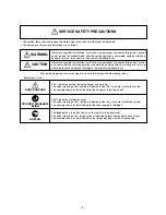
Страница 3: ...f injury or where there could be physical damage in the event of operational error Physical damage means major damage to a home furnishings and other possessions Examples of marks SHOCK HAZARD PROHIBIT DISASSEM BLING UNPLUG The indicates caution including danger and warning The actual meaning of this caution is indicated inside the or nearby illustrations or text The example shown to the left indi...

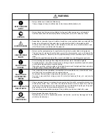
Страница 4: ...rk is included in a circuit diagram or parts list Parts mounting and routing of the wiring should be the same as that used originally For safety purposes insulating materials such as tubing or tape is sometimes used and printed circuit boards are sometimes mounted floating Also make sure that wiring is routed and clamped to avoid parts that generate heat and which use high voltage Always follow th...

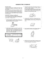
Страница 5: ...of the LCD module with the corresponding holes in the LCD cover and fasten with screws Do not strongly push on the mod ule because any impact can adversely affect the perform ance Also use caution when handling the polarized screen because it can easily be damaged CAUTION The metal edges of the LCD module are sharp so use caution to avoid in jury 3 If the panel surface becomes soiled wipe with cot...

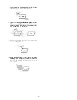
Страница 6: ...ecifications Failure to do so could result in freezing of the liquid crystal due to cold air or loss of resilience or other damage 9 Do not disassemble the LCD module Such actions could result in improper operation 10 When transporting the LCD module do not use packing containing epoxy resin amine or silicon resin alcohol or oxim The gas generated by these materials can cause loss of polarity ...

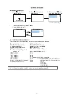
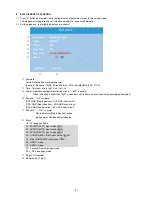
Страница 7: ...isplayed differently as shown below de pending on the setting of the receiving color system COLP PAL COLC NTSC COLS SECAM Automatic A D Adjustment PC Component 7 button Self diagnostic display ON OFF 9 button CAUTION Never try to perform initialization unless you have changed the memory IC SERVICE MODE 1 ENTERING SERVICE MODE 1 Press button once on 2 Press button again and 3 While pressing the but...

Страница 8: ...ialization is required 1 Enter the service mode then select any register item 2 Press and hold the CALL button on the Remote then press the CHANNEL s button on the TV The initialization of EEPROM IC has been complated 3 Check the picture carefully If necessary adjust any adjustment item above Perform Auto tune on the owner s manual CAUTION Never attempt to initialize the data unless EEPROM IC has ...

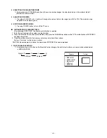
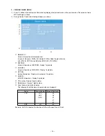
Страница 9: ...ndication is other than 000 overcurrent apt to flow and circuit parts may possibly be damaged Bus line OK is normal SCL GND Red indication SCL GND short circuit SDA GND Red indication SDA GND short circuit SCL SDA Red indication SCL SDA short circuit Bus cont OK is normal NG is abnormal Red indication when type name of semiconductor indicates 1 2 3 4 5 6 1 2 3 4 5 6 7 8 7 8 Block UV TV reception m...

Страница 10: ...58_EU_0100 E16 N EEPROM Version information of EEPROM Display 1 byte data O SUB MPU Version information of SUB MPU Display 1 byte data P OPTION Option information Display six numbers of 1 byte data Q HDMI ID HDMI ID information Display 4 byte data R CD number Display 8 digit number S Model name Display 7 digit number T Panel Vender information display The following Panel Vender and screen size are...

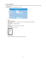
Страница 11: ... information Display RF position number 0 99 on the main screen or Input Source EXT1 2 3 HDMI etc N MAIN FORMAT Display Video and PC format information O MAIN PLL Main PLL information Display five numbers of 1 byte data P SCREEN SIZE Display the screen size as follows Q OTHER STATUS Other status information Display three numbers of 2 byte data Super live Cinema Subtitle 14 9 Wide 4 3 EXT1 1080i 50...

Страница 12: ... Back media recorder decoder CABLE HOLDER FIXING STRAP HDMI INPUT SOCKETS SCART 1 EXT1 SCART 2 EXT2 SCART 3 EXT3 IN OUT MEDIA REC TV SAT COMMON INTERFACE COMMON INTERFACE The Common Interface is for a Conditional Access Module CAM There is access for two CAMs Contact a service provider ...

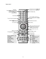
Страница 13: ...er buttons To return to the previous programme For On Standby mode To call up text services in analogue mode and interactive services in digital mode When using a TOSHIBA VCR or DVD press mto PAUSE press wto EJECT press lqto SKIP REWIND presssl to SKIP FORWARD pressrto PLAY presspto STOP press qto REWIND presssto FAST FORWARD When using menus the arrows move the cursor on the screen up down left o...

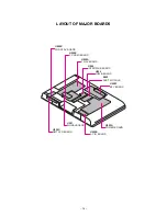
Страница 14: ...AJOR BOARDS U003E PC HDMI BOARD U003B FRONT AV BOARD U001 SIGNAL BOARD U002A POWER BOARD U002B AC IN BOARD U003C RMT LED BOARD U003A TN AV BOARD U004 LOW B BOARD U005 INTERFACE BOARD U003F KEY BOARD B002 DVB T MODULE ...

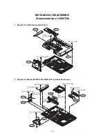
Страница 15: ... 8 SW W SBN 5 BITTB4 16 SBN 10 PP 5 16 SW W SBN 5 2 Remove the boards FRONT AV PC HDMI KEY and back center cover U003E U003F A340 A315 A320 P801 U003B PP3 8 SW W SBN 2 PP3 8 SW W SBN 2 PP3 8 SW W SBN 2 PP3 8 SW W SBN 2 PP3 8 SW W SBN 2 PP3 8 SW W SBN 2 PP3 8 SW W SBN 2 BITTB 3 12SBN 2 BITTB3 12SBN 2 BITTB4 16 SBN 2 ...

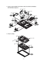
Страница 16: ...03C W661 W661 U003A U004 U002A U001 PP3 8 SW W SBN 6 PP3 8 SW W SBN 4 PP3 8 SW W SBN 8 PP3 8 SW W SBN 4 PP3 8 SW W SBN 2 BITTB3 12SBN 3 BITTB4 16 SBN 2 BITTB4 16 SBN 2 U005 PP3 8 SW W SBN 5 PP3 8 SW W SBN 4 B002 A201 B001 BITTB4 16 SBN 12 BITTB4 16 SBN BITTB4 16 SBN BITTB4 16 SBN 2 BITTB4 16 SBN 2 BITTB4 16 SBN 2 BITTB4 16 SBN 2 ...

Страница 17: ...A401 PP3 8 SW W SBN 5 BITTB4 16 SBN 10 PP 5 16 SW W SBN 5 U003E U003F A340 A320 A420 U003B PP3 8 SW W SBN 2 PP3 8 SW W SBN 2 PP3 8 SW W SBN 2 PP3 8 SW W SBN 2 PP3 8 SW W SBN 2 PP3 8 SW W SBN 2 BITTB3 12 SBN 2 BITTB3 12SBN 2 BITTB4 16 SBN 2 PP3 8 SW W SBN 5 PP3 8 SW W SBN 4 ...

Страница 18: ...W W SBN 6 PP3 8 SW W SBN 4 PP3 8 SW W SBN 8 PP3 8 SW W SBN 4 PP3 8 SW W SBN 2 BITTB3 12SBN 3 A201 B001 BITTB4 16 SBN 12 BITTB4 16 SBN BITTB4 16 SBN BITTB4 16 SBN 2 BITTB4 16 SBN 2 BITTB4 16 SBN 2 BITTB4 16 SBN 2 W661 BITTB4 16 SBN 2 W661 BITTB4 16 SBN 2 PP3 8 SW W SBN 5 PP3 8 SW W SBN 4 B002 ...

Страница 19: ... 19 PACKING DISASSEMBLY 32WLT58 37WLT58 A702B A702A A702A Y130 Y170 Y101 A701 A702B A701A A705 A705 A701B A702B A702B A702A A702A Y170 Y130 Y101 ...

Страница 20: ... Z C530 76619157 ELECTROLYTIC CHIP 16V 100UF C605 76109102 CERAMIC CHIP 50V B 1000PF K C606 76109102 CERAMIC CHIP 50V B 1000PF K C612 76664102 ELECTROLYTIC 6 3V 1000UF M 3A C631 76619102 ELECTROLYTIC CHIP 16V 47UF M C632 76092731 CERAMIC CHIP 16V B 1UF K C651 76092463 CERAMIC CHIP 16V B 0 22UF K C652 76092463 CERAMIC CHIP 16V B 0 22UF K C653 76092538 CERAMIC CHIP 10V F 1UF Z C655 76109103 CERAMIC ...

Страница 21: ...5100 CERAMIC CHIP 50V CH 10PF D 76109472 CERAMIC CHIP 50V B 4700PF K CC32 76105100 CERAMIC CHIP 50V CH 10PF D CC33 76109102 CERAMIC CHIP 50V B 1000PF K CC40 76109102 CERAMIC CHIP 50V B 1000PF K CC41 76109102 CERAMIC CHIP 50V B 1000PF K CC59 76109102 CERAMIC CHIP 50V B 1000PF K CC60 76109102 CERAMIC CHIP 50V B 1000PF K CC61 76109102 CERAMIC CHIP 50V B 1000PF K CC62 76109102 CERAMIC CHIP 50V B 1000P...

Страница 22: ...6619102 ELECTROLYTIC CHIP 16V 47UF M CV52 76619102 ELECTROLYTIC CHIP 16V 47UF M CV53 76100104 CERAMIC CHIP 25V F 0 1UF Z CV54 76100104 CERAMIC CHIP 25V F 0 1UF Z CV55 76100104 CERAMIC CHIP 25V F 0 1UF Z CV56 76619157 ELECTROLYTIC CHIP 16V 100UF CV57 76619157 ELECTROLYTIC CHIP 16V 100UF CV58 76619157 ELECTROLYTIC CHIP 16V 100UF CV59 76666471 ELECTROLYTIC 16V 470UF M CV60 76666471 ELECTROLYTIC 16V 4...

Страница 23: ...190015 CHIP RES 1 16W 473D R8246 76190015 CHIP RES 1 16W 473D R8247 76190015 CHIP RES 1 16W 473D R8248 76190015 CHIP RES 1 16W 473D R8249 76000445 CHIP JUMPER 1608TYPE R8310 76011223 CHIP 1 20W 22K OHM J R8312 76011471 CHIP 1 20W 470 OHM J R8313 76011102 CHIP 1 20W 1K OHM J R8390 76011473 CHIP 1 20W 47K OHM J R8391 76011102 CHIP 1 20W 1K OHM J R8392 76011681 CHIP 1 20W 680 OHM J R8393 76011681 CHI...

Страница 24: ...RBON FILM 1 6W 100 OHM J RE93 76366102 CARBON FILM 1 6W 1K OHM J RE94 76553101 OXIDE METAL FILM 1W 100 OHM J RE95 76552102 OXIDE METAL FILM 1 2W 1K OHM J RE96 76366473 CARBON FILM 1 6W 47K OHM J RE97 76366472 CARBON FILM 1 6W 4 7K OHM J RE98 76366473 CARBON FILM 1 6W 47K OHM J RE99 76366101 CARBON FILM 1 6W 100 OHM J RR01 76871750 CHIP 1 8W 75 OHM J RR02 76871750 CHIP 1 8W 75 OHM J RR03 76871750 C...

Страница 25: ...W 100 OHM J RV19 76011101 CHIP 1 20W 100 OHM J RV20 76011101 CHIP 1 20W 100 OHM J RV21 76011101 CHIP 1 20W 100 OHM J RV22 76011101 CHIP 1 20W 100 OHM J RV26 76011101 CHIP 1 20W 100 OHM J RV27 76011101 CHIP 1 20W 100 OHM J RV28 76011103 CHIP 1 20W 10K OHM J RV29 76011103 CHIP 1 20W 10K OHM J RV30 76019388 CHIP 1 16W 10K OHM F RV31 76019388 CHIP 1 16W 10K OHM F RV32 76019388 CHIP 1 16W 10K OHM F RV3...

Страница 26: ...D TEM2121M L505 23289022 COIL PEAKING TRF4100AT L820 23248491 COIL CHOKE 26X13 108MMH 5A TLN3641AF L821 23248491 COIL CHOKE 26X13 108MMH 5A TLN3641AF L824 23103330 FILTER FERRITE CHOKE 3 5X5X2 TEM2014AH L825 23103304 FERRITE CHOKE TEM2011AA L840 23289981 COIL PEAKING TRF4330AZ L860 23103320 COIL CHOKE TEM2011 L862 23103320 COIL CHOKE TEM2011 L870 23103320 COIL CHOKE TEM2011 L871 23103320 COIL CHOK...

Страница 27: ...R03 23318981 IC MC14053BF QR20 23205507 TRANSISTOR 2SA1576A Q QS01 23009916 IC MM1631AJBE QS02 23009614 IC CD4053BNSR QS03 23205302 TRANSISTOR 2SC3326 B F QS04 23205302 TRANSISTOR 2SC3326 B F QS05 23205325 TRANSISTOR RN2404 F QS06 23205302 TRANSISTOR 2SC3326 B F QS07 23205302 TRANSISTOR 2SC3326 B F QS08 23205506 TRANSISTOR 2SC4081 Q QS09 23205506 TRANSISTOR 2SC4081 Q QS10 23205302 TRANSISTOR 2SC33...

Страница 28: ...V06 23357762 DIODE ZENER MA8091 M DV07 23357762 DIODE ZENER MA8091 M DV08 23357762 DIODE ZENER MA8091 M DV09 23357762 DIODE ZENER MA8091 M DV10 23357762 DIODE ZENER MA8091 M DV11 23357762 DIODE ZENER MA8091 M DV12 23357762 DIODE ZENER MA8091 M DV13 23357762 DIODE ZENER MA8091 M DV14 23357762 DIODE ZENER MA8091 M DV15 23357762 DIODE ZENER MA8091 M DV16 23357762 DIODE ZENER MA8091 M DV17 23357762 DI...

Страница 29: ... 0A 34 WL56 27WL56P G CMO 27 23587825 35 00 00 34 SHP 32 23587827 0A 25 32WL58P B LPL 32 23590403 0A 15 SHP 32 23587827 00 25 32WL58P G LPL 32 23590404 00 15 SHP 37 23587829 0A 26 37WL58P B LPL 37 23590405 0A 16 SHP 37 23587829 00 26 37WL58P G LPL 37 23590406 00 16 42WL58P B LPL 42 23587831 0A 17 42WL58P G LPL 42 23587831 00 17 SHP 32 23587833 2A 25 32WLT58 LPL 32 23590407 2A 15 SHP 37 23587834 2A...

Страница 30: ...PUSH 1C1P SA081 23344505 SWITCH PUSH 1C1P SR80 23146588 RELAY DLS5D1 O M 0 15W SR81 23146584 RELAY DC12V TV5 DG 3 W661 23351321 SPEAKER ASSY 6X12 TW 8 OHM 10 SPK 1469AO X501 23153612 CRYSTAL 16 200 25PPM 25OHM XD02 23153504 CERAMIC RESONATOR 8 00MHZ 25OHM PC BOARD ASSEMBLIES U001 PD2238A1 SIGNAL scaler see previous page U002A 75001532 PC BOARD ASSY POWER PD2171A1 U002B 75001533 PC BOARD ASSY AC IN...

Страница 31: ...881 L880 D8801 L862 C868 D863 R8810 D884 R867 R8808 D880 D887 Q8601 Q864 R862 D8601 D885 Q8602 D8602 D883 R8814 C883 R8713 C866 Q860 R885 D865 R8601 R8714 C8602 C8801 T880 R8806 C864 R880 C899 D884A D8803 L883 D8804 R883 R882 C889 R8805 D886A L881 R884 C895 C890 P P 8 1 D 8 2 8 D820 GAP11 R8310 R8313 Q8312 SR80 D820A D8311 Q8310 SR81 R8312 D8313 C824 D8310 Q8311 D8312 PP84 R8715 C8701 Q870 C878 D8...

Страница 32: ...04 QT05 C662 CS90 R103 GR08 GR07 CT01 RT11 RS74 RS35 R108 GT01 D613 R163 R665 CT03 CT07 C117 Q162 RT04 CS12 CT04 CS04 R168 C661 CS03 RS402 CT08 RT06 RS91 RT12 D618 RS403 C162 C119 C163 PK01 CT06 C118 CT09 RT09 H001 GR613 GRR14 DV30 RV81 DV32 DR70 RV216 RV217 DV31 RV250 RS31 CC60 RV214 RV235 GC01 RS24 RS22 RS21 LC22 CC62 RS23 RV215 QS06 CC63 RS71 CS13 RV82 LC21 RS72 RC02 RV213 GRR17 RC01 CC61 RV212...

Страница 33: ...DV09 RV02 LV15 CV20 QS02 RS11 QS21 RS76 CS35 L104 RS12 CS08 L105 RS13 CS26 C104 CS11 CS02 GR103 C107 GR102 CS09 CS10 RS01 CS01 RS77 QS20 RS80 RS79 R608 QS52 DV34 CV53 QV10 CV50 GRV30 LV10 DV33 DV35 R652 GRV52 R6607 R655 LV25 R6603 C663 R6606 C653 Q665 Q664 Q612 R6605 GRV51 CV56 R667 R650 D612 RV16 RV17 LV16 GRV36 LV17 CV57 QV11 RV20 GRR16 CV51 QV12 CV54 QR03 CV52 RR14 RR15 RR13 RV18 GRV34 LV11 CV5...

Страница 34: ...02 RC12 DV120 CV122 RV123 R695 RV121 DV122 DV121 PV61 R696 CY650 C605 R698 2 3 23590259 2 PD2172 3 5 4 1 2 2 1 3 7 10 12 11 9 8 4 6 5 4 1 P602B P601 PV60 LC32 LC33 PV25B P661 LC31 PV61 LC32 LC33 LC31 FRONT AV BOARD PD2172B2 U003B TOP COMPONENT SIDE R 1786 9 1 23547833 8 7 6 5 4 3 2 11 10 CB02 DB02 RB10 RB15 CB03 QB04 RB08 QB07 RB18 KB01 DB01 CB01 RB24 CB04 PJ41A RB22 CB05 CB38 RB10 RB15 CB03 QB04 ...

Страница 35: ...5 RR04 GRR04 GRR05 PC HDMI BOARD PD2172B5 U003E BOTTOM FOIL SIDE PC HDMI BOARD PD2172B5 U003E TOP COMPONENT SIDE KEY BOARD PD2172B6 U003F BOTTOM FOIL SIDE KEY BOARD PD2172B6 U003F TOP COMPONENT SIDE 6 1 23547833 R 1786 RA731 DA011 DA071 RA791 RA711 RA741 RA721 DA061 RA801 RA781 RA771 SA071 SA011 SA021 SA031 RA731 DA011 DA071 RA791 RA711 PJ42C RA741 RA721 SA041 SA051 SA061 SA081 DA061 RA801 RA781 R...

Страница 36: ...09A QE65A RE36 DE32 RE35 RE38 QE35 RE33 RE37 CE36 CE35 QE35A CE66 RE30 CE34 DE31 QE60 RE66 P810A DE62 CE60 CE32 CE33 CE61 CE63 RE60 RE63 LE61 DE60 QE30 RE65 LE32 LE30 LE60 RE31 QE60A DE61 LE62 CE65 CE62 DE30 CE31 QE65 QE91 RE92 RE99 QE95A QE90A LE91 RE95 GE92 RE12 RE91 QE03 RE98 DE91 DE92 DE01 CE10 CE92 CE94 RE93 DE95 CE93 RE18 RE13 QE93 QE92 DE90 CE91 CE90 DE96 QE90 RE94 DE02 RE90 LE10 RE96 CE95 ...

Страница 37: ... 42 43 SIGNAL BOARD PD2238A1 U001 BOTTOM FOIL SIDE 1 2 3 4 A B C SIGNAL BOARD PD2238A1 U001 TOP COMPONENT SIDE 4 3 2 1 C B A ...

Страница 38: ... 6W and 5 tolerance carbon resistor unless otherwise noted as the following marks 1 2R Metal or Metal oxide of 1 2 watt 1 2S Carbon compsistion of 1 2 watt 1RF Fuse resistor of 1 watt 10W Cement of 10 watt K 10 G 2 F 1 2 CAPACITOR Unless otherwise noted in schematic all capacitor values less than 1 are expressed in F and the values more than 1 in pF All capacitors are ceramic 50V unless otherwise ...

Страница 39: ... 30 66 FUNCTION SHEET 209 31 66 D_IN_A SHEET 300 32 66 D_IN_B SHEET 301 33 66 HDMI LINC I2C SHEET 302 34 66 HDMI Rx 2 Video Audio SHEET 303 35 66 HDMI Rx 3 PWR Audio SHEET 304 36 66 HDMI AUDIO PLL SHEET 305 37 66 HDMI AUDIO DAC SHEET 306 38 66 HDMI AUDIO OUT SHEET 307 39 66 HDMI CONTROLLER SHEET 308 40 66 EEPROM1 SHEET 309 41 66 EEPROM2 SHEET 310 42 66 MICRO I O SHEET 400 43 66 OCM MEMORY I F SHEE...

Страница 40: ...VBS S ANALOG FRONT END 8DET OUT 3 YCbCr VIDEO DEC OUT 4 DCDi CVBS S MADi S DET SCALING CVBS DTV MUX BEP LVDS QR03 MC14053BF FB SW 5V 2nd CHANNEL DIGITAL INPUT A PROCESS HDMI DIGITAL INPUT B MICRO PROCESSOR STAND BY MICRO TIF VIDEO SYSTEM CVBS S RGB RGB DIGITAL 8 bit FB CVBS LVDS LCD EEPROM FLASH ROM AV LINK MICRO SCART 1 SCART 2 SCART 3 SCART 3 AV LINK EXT 4 EXT 5 FRONT PC SCART 3 SEL OUT SCART 2 ...

Страница 41: ...T2 LR5 SC3 IN LR6 OUT3 LR7 SC4 IN LR8 LR9 LR10 LR11 I2S IN1 9V RESET I2S OUT I2S CORTETZ SCALER VCD µcom Delay I2S OUT MSP_RESET DVI_SW1 DVI_SW2 ph2S WOOFER SW ph2S Variable Fix AUDIO SYSTEM AD MTS Demod SCART Input Select AD TIF SCART Output Select Source Select DA APRO TV DTV E1 SC full E2 SC full E3 SC AV E4 CS E5 front HDMI 1 A HDMI 2 A HDMI D PC DA HDMI BS_TV_MUTE EXT MUTE MUTE MONI_SW Audio ...

Страница 42: ...on and audio signal Input Phono jacks Audio L R PC Input Mini D sub 15 pin Analog RGB signal Input 3 5mm stereo jack Audio Audio Ouput Fixed Variable Phono jacks Audio L R Output to Active Super Woofer Phono socket Programme Positions 100 Stereo Nicam 2 carrier system Visible Screen Size 32WLT 80cm approx 37WLT 94cm Display 16 9 Sound output at 10 distortion Main 10W 10W Power consumption 32WLT 17...

Страница 43: ......

Отзывы: