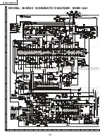
background image

2

20AR20/30

IMPORTANT SERVICE SAFETY PRECAUTION

Service work should be performed only by qualified service technicians who are throughly
familiar with all safety checks and the servicing guidelines which follow:

X-RADIATION AND HIGH VOLTAGE LIMITS

1. Be  sure  all  service  personnel  are  aware  of  the

procedures and instructions covering X-radiation. The
only  potential  source  of  X-ray  in  current  solid  state
TV receivers is the picture tube. However, the picture
tube  does  not  emit  measurable  X-Ray  radiation,  if
the high voltage is as specified in the "High Voltage
Check" instructions.
It  is  only  when  high  voltage  is  excessive  that  X-
radiation  is  capable  of  penetrating  the  shell  of  the
picture  tube  including  the  lead  in  the  glass  material.
The important precaution is to keep the high voltage
below the maximum level specified.

2. It is essential that servicemen have available at all

times an accurate high voltage meter.
The  calibration  of  this  meter  should  be  checked
periodically.

3. High voltage should always be kept at the rated value

no higher. Operation at higher voltages may cause

a failure of the picture tube or high voltage circuitry
and;also,  under  certain  conditions,  may  produce
radiation in exceeding of desirable levels.

4. When the high voltage regulator is operating properly

there is no possibility of an X-radiation problem. Every
time a color chassis is serviced, the brightness should
be tested while monitoring the high voltage with a
meter to be certain that the high voltage does not
exceed the specified value and that it is regulating
correctly.

5. Do not use a picture tube other than that specified or

make unrecommended circuit modifications  to the
high voltage circuitry.

6. When trouble shooting and taking test measurements

on a receiver with excessive high voltage, avoid being
unnecessarily close to the receiver.
Do not operate the receiver longer than is necessary
to locate the cause of excessive voltage.

WARNING

1. For continued safety, no modification of any circuit

should be attempted.

2. Disconnect AC power before servicing.
3. Semiconductor  heat  sinks  are  potential  shock

hazards when the chassis is operating.

4. The chassis in this receiver has two ground systems

which are separated by insulating material. The non-
isolated  (hot)  ground  system  is  for  the  B+  voltage
regulator circuit and the horizontal output circuit. The
isolated ground system is for the low B+ DC voltages
and  the  secondary  circuit  of  the  high  voltage
transformer.
To  prevent  electrical  shock  use  an  isolation
transformer  between  the  line  cord  and  power
receptacle,  when  servicing  this  chassis.

SERVICING  OF  HIGH  VOLTAGE  SYSTEM
AND  PICTURE  TUBE

When  servicing  the  high  voltage  system,
remove  the  static  charge  by  connecting  a
10k  ohm  resistor  in  series  with  an  insulated
wire  (such  as  a  test  probe)  between  the  pic-
ture  tube  ground  and  the  anode  lead.  (AC
line  cord  should  be  disconnected  from  AC
outlet.)

1. Picture  tube  in  this  receiver 

employs 

integral

implosion  protection.

2. Replace  with  tube  of  the  same  type  number  for

continued  safety.

3. Do not lift picture tube by the neck.
4. Handle  the  picture  tube  only  when  wearing

shatterproof  goggles  and  after  discharging  the  high
voltage anode completely.

Содержание 20AR20

Страница 1: ...CATIONS Specifications are subject to change without prior notice SERVICE MANUAL 20AR20 30 MODELS 20AR30 20AR20 POWER INPUT 110 220 V AC 50 60 Hz POWER RATING 20AR20 88 W 20AR30 98 W PICTURE SIZE 1 194cm2 185sq inch CONVERGENCE Magnetic SWEEP DEFLECTION Magnetic FOCUS QPF Electrostatic INTERMEDIATE FREQUENCIES Picture IF Carrier Frequency 45 75 MHz Sound IF Carrier Frequency 41 25 MHz Color Sub Ca...

Страница 2: ...es not exceed the specified value and that it is regulating correctly 5 Do not use a picture tube other than that specified or make unrecommended circuit modifications to the high voltage circuitry 6 When trouble shootingand taking test measurements on a receiverwith excessivehigh voltage avoid being unnecessarily close to the receiver Do not operate the receiver longer than is necessary to locate...

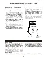
Страница 3: ...5 F capacitorin series with all exposed metal cabinet parts and a known earth ground such as electrical conduit or electrical ground connected to earth ground Use an AC voltmeter having with 5000 ohm per volt or higher sensitivity to measure the AC voltage drop across the resistor For continued protection replacement parts must be identical to those used in the original circuit The use of substitu...

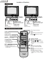
Страница 4: ...PUT Press Switch to external video input mode Press again Switch to TV mode See page 17 CHANNEL UP DOWN Selects next higher channel Selects next lower channel See pages 15 16 for channel presetting Moves the mark of the MENU screen MENU Press Accesses MAIN MENU Press again Exits MAIN MENU DISPLAY Press Displays receiving channel for 4 seconds Press again Removes display Temporarily displays receiv...

Страница 5: ...ration of the horizontal oscillator does not stop in step 5 the circuit must be repaired before the set is returned to the customer HIGH VOLTAGE CHECK High voltage is not adjustable but must be checked to verify that the receiver is operating within safe and efficient design limitations as specified checks should be as follows 1 Connect an accurate high voltage meter between ground and anode of pi...

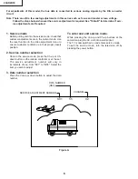
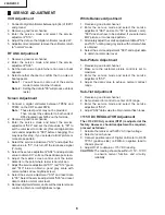
Страница 6: ...u to ensure customer controls are in their proper reset position 2 Service number selection Once in the service mode press the Ch up or Ch down button on the remote controller or at the set The service adjustment number will vary in increments of one from S01 to M05 Select the item you wish to adjust 3 Data number selection Press the Vol up or down button to adjust the data number To enter and exi...

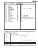
Страница 7: ...No Vertical OP OPTION Set to each model 80 00 FF Must be set to 08 20AR20 09 20AR30 M01 MTS LEVEL 0A 00 0F M02 STEREO VCO 20 00 3F M03 FILTER 1C 00 3F M04 LOW SEPARATION 20 00 3F M05 HIGH SEPARATION 1B 00 3F NECESSARY UNNECESSARY ADJUSTMENT NOTES PART REPLACED IC2001 IC2101 X IC3001 20AR30 CRT X IC201 X X Data is stored in IC2101 Adjust items related to picture tube only Holding down both the CH u...

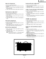
Страница 8: ...rely seen 7 Adjust the serviceadjustments S11 red S12 green and S13 blue to obtain a good grey scale with normal whites at low brightness level 8 Select the service adjustment S19 and reset data to 00 Select the service adjustment S03 and reset data to obtain normal color level 9 Removedigitalvoltmeter and reset the masterscreen control to obtain normal brightness range White Balance Adjustment 1 ...

Страница 9: ...hen adjust another data retrace line will be appear Horizontal Position Adjustment 1 Receive a good local channel 2 Enter the service mode and select the service adjustment S07 3 Adjust S07 data value so that picture is centered Caption Position Adjustment Horizontal 1 Receive a good local channel 2 Enter the service mode and select the service adjustment S18 3 A black text box appears on the scre...

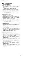
Страница 10: ...n 14 of IC3001 Stereo pilot signal 9 4kHz 600mVrms 2 Enter the service mode and select the service adjustment M03 3 Adjust the data at the point where OK appears on the screen The OK represents the approximate center of the adjustable range of the data Separation Adjustment 1 Connect the rms voltmeter to pin 39 of IC3001 2 Receive the following composite stereo signal 1 Composite stereo signal 30 ...

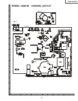
Страница 11: ...11 20AR20 20AR30 6 5 4 3 2 1 A B C D E F G H MODEL 20AR20 CHASSIS LAYOUT PWB C PWB B PWB A ...

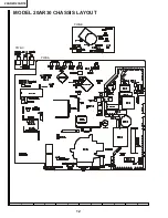
Страница 12: ...12 20AR20 20AR30 6 5 4 3 2 1 A B C D E F G H MODEL 20AR30 CHASSIS LAYOUT PWB C PWB A PWB B ...

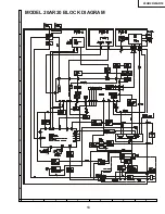
Страница 13: ...13 20AR20 20AR30 6 5 4 3 2 1 A B C D E F G H MODEL 20AR20 BLOCK DIAGRAM ...

Страница 14: ...14 20AR20 20AR30 6 5 4 3 2 1 A B C D E F G H MODEL 20AR30 BLOCK DIAGRAM ...

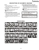
Страница 15: ...l controls set for normal picture unless otherwise indicated 2 All voltages measured with 1000µ V B W or Color signal WAVEFORM MEASUREMENT CONDITIONS 1 Photographs taken on a standard gated color bar signal the tint setting adjusted for proper color The wave shapesat the red green and blue cathodesof the picture tube depend on the tint color level and picture control 2 indicates waveform check poi...

Страница 16: ...16 20AR20 20AR30 6 5 4 3 2 1 A B C D E F G H 8 7 10 9 6 5 4 3 2 1 A B C D E F G H MODEL 20AR20 SCHEMATIC DIAGRAM MAIN Unit VSP9050PB218A VSP9050PB218A VTST5UF78 ...

Страница 17: ...17 20AR20 20AR30 6 5 4 3 2 1 A B C D E F G H 17 16 19 18 15 14 13 12 11 10 H0106GJ H0201PE ...

Страница 18: ...18 20AR20 20AR30 6 5 4 3 2 1 A B C D E F G H MODEL 20AR30 SCHEMATIC DIAGRAM MAIN 1 Unit 8 7 10 9 6 5 4 3 2 1 A B C D E F G H 16 16 VSP9050PB25WA VSP9050PB25WA VTST5UF78 CILG0107PE ...

Страница 19: ...19 20AR20 20AR30 6 5 4 3 2 1 A B C D E F G H 17 16 19 18 15 14 13 12 11 10 2 2 H0106GJ H0201PE ...

Страница 20: ...20 20AR20 20AR30 6 5 4 3 2 1 A B C D E F G H MODEL 20AR30 SCHEMATIC DIAGRAM MAIN 2 Unit ...

Страница 21: ...21 20AR20 20AR30 6 5 4 3 2 1 A B C D E F G H SCHEMATIC DIAGRAM FRONT AV and CRT Unit 20AR30 20AR20 ...

Страница 22: ...22 20AR20 20AR30 6 5 4 3 2 1 A B C D E F G H PWB A MAIN Unit Wiring Side PRINTED WIRING BOARD ASSEMBLIES ...

Страница 23: ...23 20AR20 20AR30 6 5 4 3 2 1 A B C D E F G H PWB A MAIN Unit Chip Parts Side ...

Страница 24: ...24 20AR20 20AR30 6 5 4 3 2 1 A B C D E F G H PWB C FRONT AV Unit Wiring Side PWB B CRT Unit Wiring Side ...

Страница 25: ...79 AD100067 AD100067 AD100067 AD100084 AD100077 AD100078 AD100073 AD100069 AD100073 AD100080 AD100081 AD100069 AD100076 AD100074 AD100079 VHiKA78S05P 1 RH iX2701CEN1 RH iX2933CEZZ VHiTDA7056A 1 VHiTDA7056A 1 VHiTA8403K 1 RH iX1779CEZZ VHiKA7809Pi 1 VHiKA7809AP 1 RH iX2946CEZZ VHiPST994C 1 VHiM24C01B 1 VHiBR24C01 1 VHiAT24C01 1 VHiCXA2053Q 1 AD100183 AD100087 AD100088 AD100187 AD100187 AD100186 AD1...

Страница 26: ...63J VCEA0A1HW475M VCEA0A1EW477M VCKYPA2HB391K VCQYTA1HM473J VCQYTA1HM103J VCEAGA1VW107M VCKYPA2HB102K VCEA0A1VW477M VCQYTA1HM473J VCEACA1HC225M VCEACA1HC225J VCKYPA1HB102K VCKYCY1HF103Z VCSATA1CE225K VCEA0A1HW225M VCKYPB2HB562K VCEAGH2CW227M VCFPPD3CA872H VCKYP A2HB222K VCFPPJ2EB474J VCEA0A1HW225M VCKYCY1HF103Z VCEA0A1HW105M AD100177 AD100130 AD100135 AD100127 AD100121 AD100155 AD100160 AD100155 A...

Страница 27: ...0A1CW477M RC KZ0341CEZZ VCEA0A2EW106M VCKYPA2HB102K VCEA0A1CW337M VCQYTA1HM104J VCQYTA1HM223J VCEA0A1HW474M VCCCCY1HH120J VCEA0A1HW104M VCEA0A1HW104M VCEA0A1HW104M VCCCCY1HH820J VCKYCY1EF104Z VCEA0A1HW335M VCEA0A1HW335M VCCCCY1HH101J VCCCCY1HH101J VCEA0A1CW106M VCCCCY1HH101J VCCCCY1HH101J VCCCCY1HH101J VCCCCY1HH101J VCEA0A1AW107M VCEA0A1HW105M VCQYTA1HM104J VCCCPA1HH101J VCEA0A1AW107M VCCCPA1HH560...

Страница 28: ...0 AD100281 AD100251 AD100251 AD100253 AD100253 AD100199 AD100199 AD100252 AD100252 AD100217 AD100251 AD100200 AD100282 AD100274 AD100236 AD100217 AD100280 AD100280 AD100280 AD100280 AD100200 AD100251 AD100252 AD100221 AD100251 AD100217 AD100250 AD100250 AD100280 AD100250 AD100260 Description 2 2 1W M Film 0 47 1W M Film 2 7 10W Cement 1 5 5W Cement 180k 1 2W Carbon 180k 1 2W Carbon 2 7k 3 0W M Ox ...
Страница 29: ... Ox 47 1 8W Carbon 220 1 8W Carbon 20AR30 220 1 8W Carbon 20AR30 1 0M 1 16W M Ox 20AR30 100k 1 16W M Ox 20AR30 62k 1 16W M Ox 20AR30 3 3k 1 16W M Ox 20AR30 3 0k 1 16W M Ox 20AR30 3 9k 1 16W M Ox 20AR30 1 0k 1 16W M Ox 20AR30 1 0k 1 16W M Ox 20AR30 2 2 1 8W Carbon 20AR30 Power Vol Down Vol Up Ch Down Ch Up Relay Relay Fuse 3 15A Ferrite Bead Ferrite Bead Ferrite Bead Ferrite Bead Ferrite Bead Ferri...

Страница 30: ... 220 1 8W Carbon 120 1 8W Carbon 12k 1W M Ox 3 3k 1 2W Carbon 1 0k 1 8W Carbon 390 1 8W Carbon 560 1 8W Carbon 1 5k 1 8W Carbon 4 7 1 8W Carbon Plug 5 pin GBN Plug 4 pin YBN C R T Socket 4 7 1 8W Carbon UBATU0001AJZZ AD100104 AD100094 AD100033 AD100105 Battery Box Unit A1HB271K A1HB271K A1HB271K QJAKE0150CEZZ QJAKE0185CEZZ QJAKE0184CEZZ QPLGN0561CEZZ VP DF151K0000 VCKYP VCKYP VCKYP RC KZ0016CEZZ V...

Страница 31: ...30 PACKING OF THE SET Use tape to seal the packing case Packing Case FRONT Buffer Material Polyethylene Foam Wrap Polyethylene Bag MARK Not Replacement Items Operation manual Infrared R C Unit AC Adapter Warranty Card Batteries CINS 7104WEV0 SPAKX0002GJZZ SPAKP0102GJZZ SPAKC0137GJZZ ...

Страница 32: ...nical photocopying recording or otherwise without prior written permission of the publisher TOSHIBA AMERICA CONSUMER PRODUCTS INC TOSHIBA DE MEXICO S A DE C V LATIN AMERICA DIVISION HEAD OFFICE 82 TOTOWA ROAD WAYNE NEW JERSEY 07470 TEL 973 628 8000 SIERRA CANDELA NO 111 6 PISO COL LOMAS DE CHAPULTEPEC 11000 MEXICO D F TEL 5 202 26 77 1900 NORTH WEST 84TH AVENUE MIAMI FLORIDA 33126 TEL 305 470 9355...

Отзывы: