


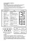
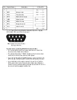
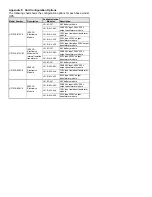
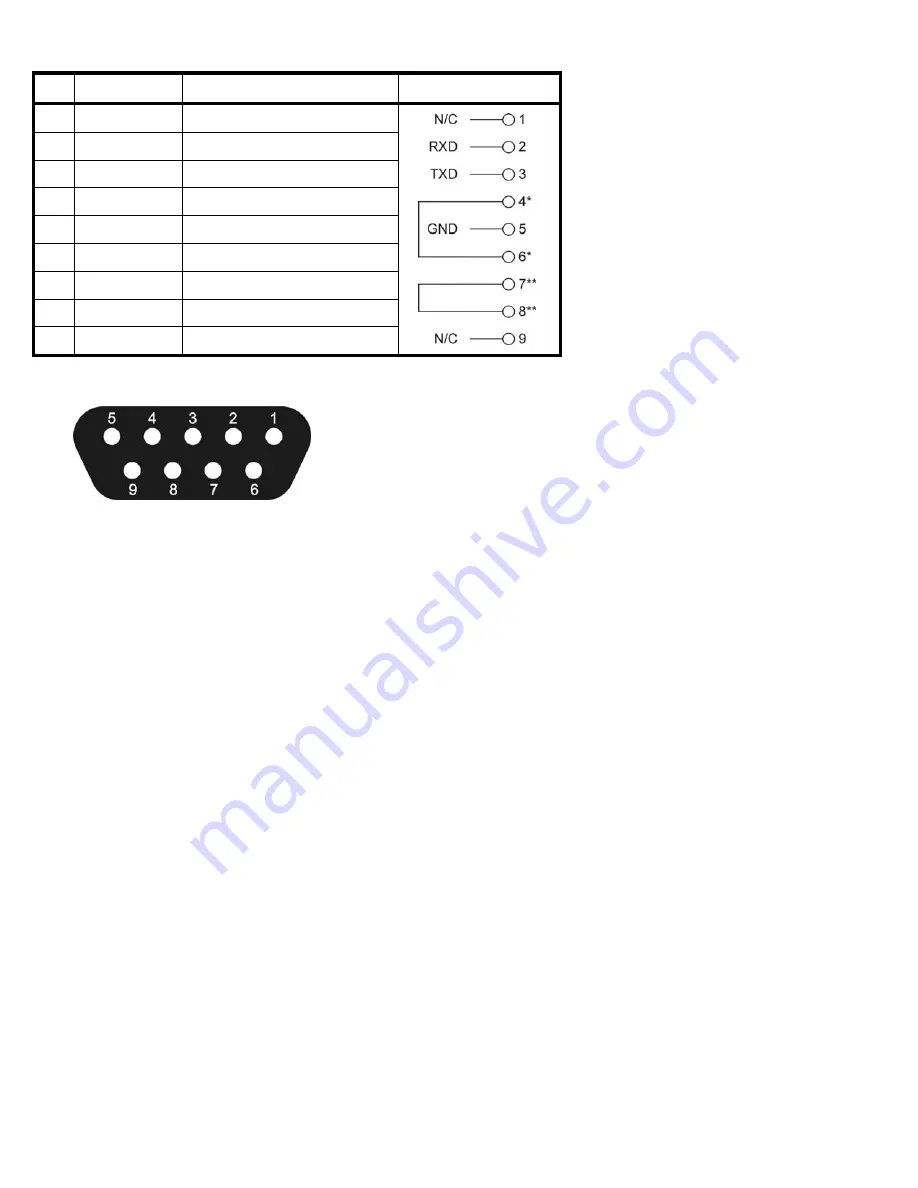
Pin
Signal Name
Description
In the UPS
1 -
2 RXD
Receive
data
3 TXD
Transmit
data
4
DTR
Data terminal ready
5 GND
Signal
ground
6
DSR
Data set ready
7
RTS
Request to send
8
CTS
Clear to send
9 -
(*) (**) These pins are tied together internal to the UPS. Signals
DTR, DSR, RTS, and CTS are not used.
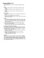
Special notes concerning RS-232C communication
• For Toshiba UPS protocol and command structure refer to the
Communication Option User Manual
• The optional RemotEye™ SNMP interface is the recommended
method for communication with the UPS system.
• If an optional RemotEye™ SNMP interface card is installed in the
UPS only one method (SNMP or RS-232C) will function at a time.
• For a description of the cable required to connect to a Toshiba
UPS system refer to the Communication Option User Manual or
contact Toshiba’s UPS Marketing Department at (800) 231-1412 or
by e-mail at [email protected].
DB9 Female Connector Outline
(facing connector)
Содержание 1500 VA
Страница 41: ...Notes ...
Страница 42: ...Notes ...


