background image

TORONTO TOOL MANUFACTURING INC.


Pro-Cut 50


User Manual 


Pro-Cut 50 User Manual Version 03:02:115:04 

The contents of this manual are subject to change without notice. For any updates or improvements please visit our web 
site at:                                                                        www.torontotool.com 


Содержание Pro-Cut 50

Страница 1: ...URING INC Pro Cut 50 User Manual Pro Cut 50 User Manual Version 03 02 115 04 The contents of this manual are subject to change without notice For any updates or improvements please visit our web site at www torontotool com ...

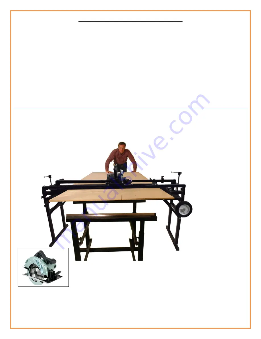
Страница 2: ... back The fact that a side fence moves means it will have some play and a good possibility of error Next Generation Table Saw The new Pro Cut 50 is the next generation table saw with numerous features and benefits to address the inherent disadvantages of a table saw The Pro Cut 50 rip cuts material like a conventional table saw but unlike a conventional table saw the material is fully guided on bo...

Страница 3: ...hipping The only proven method for eliminating tear out or chipping is by kerf cutting A pre cut or kerf blade is only found on the most expensive table saws A Different Approach The Pro Cut 50 uses an entirely different approach to crosscutting The board or panel is locked in place on the Pro Cut 50 and the saw slides through the material on precision guide rails No more reaching over the panel o...

Страница 4: ... to name a few You can also dado both side panels of a cabinet at the same time on the Pro Cut 50 This is perfect for exact placement of shelves in cabinets of any height Routing cutouts for inlays in any project is also a breeze on the Pro Cut 50 The Pro Cut 50 comes with the router insert plate 2 router guide stops and 2 panel stops for quick and easy set up for routing any project Virtually any...

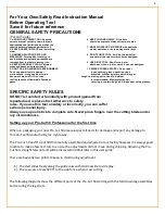
Страница 5: ...se caught in moving parts Nonslip footwear tool in presence of flammable liquids or is recommended Wear protective hair gases covering to contain long hair Always wear safety glasses SPECIFIC SAFETY RULES DO NOT let comfort or familiarity with product gained from repeated use replace strict adherence to safety rules If you use this tool unsafely or incorrectly you can suffer serious personal injur...

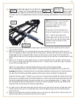
Страница 6: ...h the washer and wing nut and hand tighten Follow the same procedure for the leg strut on the opposite side of this leg assembly Follow the same procedure for the leg assembly on the other end of the Pro Cut 50 Sled Guide Rail Sub Frame 1 The Sled Guide Rail Sub Frames have a 5 8 x 14 Clamp Screw and 5 8 Clamp Screw Nut 2 There are 2 knobs on either side of the Pro Cut 50 Sub Frame Fig 2 These are...

Страница 7: ...Sled Guide Rail Sub Frame to allow independent adjustment of each Sled Guide Rail The slots will be used to allow the exact positioning of the Sled Guide Rails explained later Side Fence The side fence assembly has 4 adjustment points The side fence base has two slots to allow squaring of the entire side fence assembly to the saw blade fig 6 The clamp rails have slots to allow alignment of the sid...

Страница 8: ...crews on either end of the Pro Cut 50 scale and move the entire scale until the Pro Cut 50 scale measurement is identical to the measurement on your hand held measuring tape Tighten the two thumb screws on the Pro Cut 50 measuring scale Your Pro cut 50 scale is now identical to your hand held scale Saw Blade Depth Gauge IMPORTANT To achieve the best results when cutting material with a minimum amo...

Страница 9: ...pposite side of your board or panel The Aux Side Fence should be placed firmly against the side of your board or panel but not so tight as to restrict the smooth feed of the material Once you have the Aux Side Fence set lock the 2 toggle clamps to the clamp rails of the Pro Cut 50 and you are ready to cut Pro Cut 50 adjustment This section will cover the adjustment of the Pro Cut 50 Take your time...

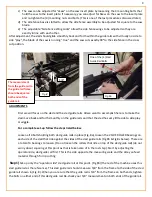
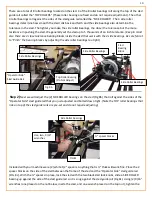
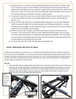
Страница 10: ... For a complete set up follow the steps listed below Loosen all 4 bolts holding both sled guide rails in place Fig 8a loosen the 2 SIDE ROLLER bearings on each side of the sled that ride against the sides of the sled guide rails Fig 8b Fig 8c below There are a total of 4 bearings to loosen Do not loosen the rollers that ride on top of the sled guide rail do not worry about squaring at this point a...

Страница 11: ...t Step 2 Next we will adjust the 2 SIDE ROLLER bearings on the sled Fig 8b that roll against the sides of the Operator Side sled guide rail that you just adjusted and bolted down tight Note the TOP roller bearings that ride on top of the sled guide rails are pre set and do not require adjusting Included with your machine were 2 white 1 2 spacers Anything that is thick will work fine Place the 2 sp...

Страница 12: ...ome variance between machines but the important point is to be sure the measurement between the sled guide rails is the same on both ends of the machine If you measure 13 1 16 on the inside of the guide rails on one end of the machine then the measurement between the inside sled guide rails should be exactly 13 1 16 on the other end of the machine NOTE the corners of the sled guide rails are round...

Страница 13: ... of paper NOTE To make it easier you can tape the feeler gauge or paper to the sled guide rail until you have finished your adjustment Slide the side roller bearing snug up against the feeler gauge and tighten Leave the feeler gauge in place until you have adjusted the other side roller bearing in the same manor With both side roller bearings adjusted and tightened remove the feeler gauges and mov...

Страница 14: ...earings with your finger The internal white bearing blocks are called floating bearing blocks designed to move freely within the sled housing You should be able to slide each of the 4 sled internal white bearing blocks back and forth within the sled housing with your finger 5 There should be very little side to side play when you wiggle the sled Step 5 Adjusting the Side Fence for Square In this s...

Страница 15: ... be out of the way for this adjustment Be sure the saw is unplugged and place an elastic band over the saw blade guard lever and loop it over a locking knob on the sled This will hold the saw blade guard out of the way until you complete this adjustment If you do not have a large T Square you can use a 4 x 4 panel such as melamine or MDF Be sure the panel you use is perfectly square on all sides M...

Страница 16: ... to the wings as before and loosen only both wing locking bolts For slight adjustments you can square the wings to the saw blade Then slide the wing locks back up to the wings and tighten the wing lock bolts that hold the wing lock assy to the clamp rail of the Pro Cut 50 frame 7 Now that the side fence is exactly square to the saw blade check to be sure the saw blade is running true Show in Fig 8...

Страница 17: ...erations you will probably leave the sled push rail installed however for small routing projects it may be easier to remove the sled push rail Remote Power Switch and Saw Trigger Lock Sled Push Handle Push Rail quick Release Pin The power switch box is used to plug the power tool into and comes equipped with a power lock out Saw Trigger Lock Fig 21 Fig 22 Fig 23 Remote Power Switch ...

Страница 18: ... The table top insert has been designed from standard 5 8 thick melamine material available at most building supply stores and is easy to replace should it become necessary The table top insert that comes with the Pro Cut 50 will last for years but since it is possible to accidently cut into the table top in some cases more so with the router it is important the table top insert is made of a mater...

Страница 19: ... plate under the two back lock screws as shown in Fig 24 25 and tighten the back lock screws against the insert plate 3 Swing the front insert lock arms over the saw insert plate and screw down the lock knob screws tightly against the insert plate Fig 24 Fig 25 Fig 26 Slide insert plate under the back lock screws Tighten both back insert lock screws Swing the front insert lock arms over the insert...

Страница 20: ... The router insert plate is exactly the same size as the saw insert plate so interchanging the two requires no adjustment Fig 27 Fig 28 Fig 29 Loosen all 4 lock screws and remove the saw insert from the sled Turn the saw 900 and place the saw insert back into the sled for rip cutting Slide the saw insert plate under the back screw locks and screw the locks down tight against the saw insert plate S...

Страница 21: ... the router directly to the Pro Cut 50 router insert plate Fig 31 Adjusting the Saw Carriage Height The Pro Cut 50 is pre set to cut material up to without adjustment For thicker material the Pro Cut 50 has adjustable height up to 3 1 2 To raise the height of the saw carriage simply unlock the 4 lock knobs Fig 32 33 located on either end of the Pro Cut 50 and screw the clamp screw up Fig 34 on bot...

Страница 22: ... guided on both sides when using the Aux Side Fence thus eliminating feed errors The fence is fixed at exactly 90o to the saw thus eliminating any side fence error as can be experienced on conventional table saws For cutting angles you simply tilt the saw to any desired angle See Fig 41 42 43 Fig 32 Fig 33 Fig 34 Fig 35 Fig 36 Clamp Screw Lock Knobs Lock Knob Lock Knob Spacer Block Place height Sp...

Страница 23: ... To rip cut a board or panel 1 Unplug the saw and raise the blade all the way up 2 Place the saw in the correct orientation for rip cutting in the Pro Cut 50 sled 3 Slide the sled to the desired measurement using the built in measuring scale Tip be sure you set the saw blade on the proper side of the cut mark to be sure your cut material is the size you want 4 Lock the sled See Fig 40 5 Be sure th...

Страница 24: ...ou can pre cut or kerf cut the board or panel by raising the blade to cut a 1 8 kerf cut Run the material all the way through For the second cut set the blade depth so the blade extends below the material to be cut and make the second cut Blade selection is also important Use a minimum of a 40 tooth thick kerf blade You can also use a 50 60 or even 80 tooth blade for an even smoother cut The down ...

Страница 25: ...e along with the blade depth will determine the accuracy of cut There should be a minimum amount of blade flex to prevent the blade from flexing or wandering during the rip cut Excessive blade flex will result in binding and most likely produce a wavy cut The same rules for rip cutting on a table saw hold true for rip cutting on the SRG 50 and the Pro Cut 50 and therefore you will want to choose a...

Страница 26: ...w or in close proximity to the blade in any circumstance when rip cutting or performing any other application This may result in serious injury When rip cutting always use a push stick to complete the rip cut of all material Cross Cutting on The Pro Cut 50 Cross Cutting Has Never Been Easier The Pro Cut 50 uses an entirely different approach to crosscutting The board or panel is locked in place on...

Страница 27: ...mped These clamps along with a number of other accessories are available for purchase through our web site www torontotool com One clamp is generally sufficient but you may opt to use 2 clamps on either side of the panel 7 Make the cut TIP For a factory edge in sensitive material that is prone to chipping such as melamine you can pre cut or kerf cut the board or panel by raising the blade to cut a...

Страница 28: ...e sure there is a good sharp thick kerf carbide blade with at least 40 teeth mounted in the saw for this next step With the saw up plugged set the saw in the Rip Cut position in the Pro Cut 50 sled with the saw blade locked at its full up position Open the saw blade guard using the saw blade lever and lower the blade on the saw so the blade is slightly above the table top insert 2 We will allow 2 ...

Страница 29: ...s a unique set up in that the router will move across or through material that is clamped to the clamping rails of the pro Cut 50 For example you can make a jig to cut arcs or even full circles using the Pro Cut 50 The router can lock at any position along the guide rails and your jig can clamp at any position on the clamping rails of the Pro Cut 50 It is easy to make a jig that pivots to move a p...

Страница 30: ...ue another board s or panel to the top of your project and continue routing Great for making true raised panel doors for example Make moldings of any length contour or width up to 50 The entertainment center shown above Fig 48 is easy to build and takes half the time using the Pro Cut 50 All of the cabinet parts including panels doors moldings and trim are manufactured using the Pro Cut 50 The dad...

Страница 31: ... so the router will stop at the measured marks on your panel Fig 68 If you are routing a small panel and the panel stops will not work then clamp a board to the clamp rails of the Pro Cut 50 positioned in such a way to act as a stop 4 To rout in the Y direction lock the sled in place using the 2 sled lock knobs and push the panel back and forth between the two guides Fig 52 5 To router in the X di...

Страница 32: ...oject material to allow for placement of the panel stops The guides you make can use toggle clamps as show in Fig 55 or you can simply use C clamps to lock your guides in place We have made cut outs in the aluminum of the guide rails as shown in Fig 55 to allow the router bit to cut into the guides for side routing of the project material Fig 54 Fig 55 Toggle Clamps Push Rail Guides Guide Lock X A...

Страница 33: ...32 Fig 56 Fig 57 Fig 58 Fig 59 Fig 60 Fig 61 Layout Marks Layout Mark ...

Страница 34: ...to 4 Line the router bit up to the the first project layout mark position against the sled and second layout mark lock in place Fig 65 Fig 66 Fig 67 5 Slide the second router 6 Line the router bit up to the 7 Line the router bit up to the last guide stop into position third layout mark and lock a layout mark and lock the second against the sled and panel stop in place panel stop in place lock in p...

Страница 35: ...and bottom of any cabinet Measure clamp and router it s that easy Shown below is a set up for routing dados in both side panels of a cabinet We have clamped the two panels to be routed on one end so they stay perfectlyaligned For this application router guide stops are positioned on the clamp guide rail to stop the router at the desired locations for the shelf inset distance Guide Stop Guide Stop ...

Страница 36: ...uble Roller stands The SRG 29 Double Roller Stands are used in conjunction with the Pro Cut 50 and SRG 50 as in feed and out feed rollers for smooth rip cutting of large panels without assistance They are also perfect for supporting long boards and planks for many other applications such as with your planer miter saw or jointer to name a few The SRG 29 Double Roller Stands are easy to transport ea...

Страница 37: ...le for injuries accidental or otherwise death to person or damage to property or for incidental and contingent special or consequential damages arising from the use of our products Not Covered Under Terms of Warranty Damage due to fire theft floods and or acts of God misuse abuse negligence or accidents product has been modified in any way product used for other than the intended use improper asse...

Страница 38: ...16 250 6728 Be sure to visit our web site to view or growing list of how to videos and our workshop tips and tricks You can also visit the dealer location section of our web site to find a dealer near you The contents of this manual are subject to change without notice For any updates or improvements please visit our web site at www torontotool com ...

Отзывы: