Adjusting the Anti-Scalp
Rollers
Whenever you change the height of cut, it is recommended to
adjust the height of the anti-scalp rollers.
1.
Disengage the PTO, move the motion-control levers to
the N
EUTRAL
-
LOCK
position, and engage the parking
brake.
2.
Shut off the engine, remove the key, and wait for all
moving parts to stop before leaving the operating
position.
3.
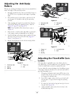
After adjusting the height of cut, adjust the rollers by
removing the flange nut, bushing, spacer, and bolt
(
, and
Note:
The 2 middle rollers do not have a spacer
).
4.
Select a hole so that the anti-scalp roller is positioned
to the nearest corresponding height of cut desired.
5.
Install the flange nut bushing, spacer, and bolt. Torque
the bolt to 54 to 61 N∙m (40 to 45 ft-lb) (
,
, and
).
6.
Repeat this adjustment on the other anti-scalp rollers.
g001102
Figure 31
1.
Anti-scalp roller
4.
Flange nut
2.
Spacer
5.
Bolt
3.
Bushing
g001101
Figure 32
1.
Anti-scalp roller
3.
Flange nut
2.
Bushing
4.
Bolt
g001100
Figure 33
1.
Flange nut
4.
Anti-scalp roller
2.
Spacer
5.
Bolt
3.
Bushing
Adjusting the Flow Baffle Cam
Locks
This procedure is applicable only to machines with the
flow-baffle locks. Certain models have nuts and bolts in place
of the flow-baffle locks and can be adjusted the same.
You can adjust the mower-discharge flow for different types
of mowing conditions. Position the cam locks and baffle to
give the best quality of cut.
1.
Disengage the blade-control switch (PTO), move the
motion-control levers to the N
EUTRAL
-
LOCK
position,
and engage the parking brake.
2.
Shut off the engine, remove the key, and wait for all
moving parts to stop before leaving the operating
position.
3.
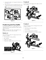
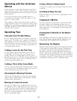
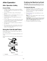
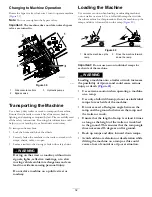
To adjust the cam locks, swing the lever up to loosen
the cam lock (
4.
Adjust the baffle and cam locks in the slots to the
desired discharge flow.
28
Содержание Z593-D Z Master 74264TE
Страница 75: ...Schematics g012068 g012068 Wire Diagram Rev A 75 ...
Страница 76: ...Notes ...
Страница 77: ...Notes ...
Страница 78: ...Notes ...


