background image

g021420

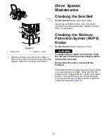
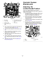
Figure 61

1.

ROPS knob (locked
position)

3.

Roll bar in the upright
position

2.

Pull the ROPS knob out,
and rotate it 90 degrees to
change the roll bar position

4.

Roll bar in the folded
position

Adjusting the Tracking

1.

Disengage the blade-control switch (PTO).

2.

Drive to an open flat area, move the
motion-control levers to the N

EUTRAL

-L

OCK

position.

3.

Move the throttle midway between fast and slow.

4.

Move both motion-control levers all the way
forward until they both hit the stops in the T-slot.

5.

Check which way the machine tracks.

If it tracks to the right, loosen the bolts and
adjust the left stop plate rearward on the
left T-slot until the machine tracks straight
(

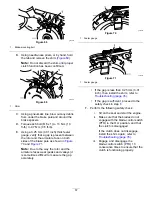
Figure 62

).

If it tracks to the left, loosen the bolts and
adjust the right stop plate rearward on the
right T-slot until the machine tracks straight
(

Figure 62

).

6.

Tighten the stop plate (

Figure 62

).

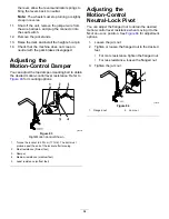
g027424

Figure 62

Left control lever shown

1.

Control lever

3.

Stop plate

2.

Bolt

Checking the Tire Pressure

Service Interval:

Every 50 hours/Monthly (whichever

comes first)

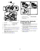
Maintain the air pressure in the front and rear tires at
90 kPa (13 psi). Uneven tire pressure can cause an
uneven cut. Check the tires when they are cold to get
the most accurate pressure reading.

g001055

Figure 63

54


Содержание Z Master Professional 5000 Series

Страница 1: ...rofessional 5000 Series Riding Mower with 60in or 72in TURBO FORCE Side Discharge Mower Model No 74933 Serial No 400000000 and Up Model No 74934 Serial No 400000000 and Up Register at www Toro com Ori...

Страница 2: ...our product properly and to avoid injury and product damage You are responsible for operating the product properly and safely You may contact Toro directly at www Toro com for product safety and opera...

Страница 3: ...r 41 Servicing the Engine Oil 43 Servicing the Spark Plug 47 Checking the Spark Arrester 48 Fuel System Maintenance 48 Inspecting the LPG System 48 Servicing the Electronic Fuel Injection System 49 El...

Страница 4: ...hine without all guards and other safety protective devices in place and working on the machine Keep clear of any discharge opening Keep bystanders a safe distance away from the machine Keep children...

Страница 5: ...degrees Use the slope chart to determine the degree of slope of hills before operating Do not operate this machine on a slope greater than 15 degrees Fold along the appropriate line to match the recom...

Страница 6: ...o 149 N m 85 to 110 ft lb decal99 8936 99 8936 1 Machine speed 4 Neutral 2 Fast 5 Reverse 3 Slow decal106 5517 106 5517 1 Warning do not touch the hot surface decal107 3069 107 3069 1 Warning there is...

Страница 7: ...ng stay away from moving parts keep all guards in place decal114 4466 114 4466 1 Main 25 A 3 Charge 25 A 2 PTO 10 A 4 Auxiliary 15 A decal116 5988 116 5988 1 Parking brake engaged 2 Parking brake dise...

Страница 8: ...lug nut torque 95 ft lb 129 N m 4x 2 Wheel hub nut torque 235 ft lb 319 N m 3 Read and understand the Operator s Manual before performing any maintenance check torque after first 100 hours then every...

Страница 9: ...attery Symbols Some or all of these symbols are on your battery 1 Explosion hazard 6 Keep bystanders a safe distance from the battery 2 No fire open flame or smoking 7 Wear eye protection explosive ga...

Страница 10: ...l full replacement tank s by aligning the center hole on the tank collar over the mounting tab index pin 3 Close the fuel valve s on the tanks by rotating them clockwise continue to run the engine 9 L...

Страница 11: ...aulic fluid every 50 operating hours 3 Check the tire pressure every 50 operating hours 2 Read the Operator s Manual for information on lubricating the machine 4 Read the Operator s Manual before serv...

Страница 12: ...ing the machine on slopes Raising the cutting units while operating on slopes can cause the machine to become unstable 1 Warning read the Operator s Manual do not operate this machine unless you are t...

Страница 13: ...decal136 5508 136 5508 1 Belt routing 13...

Страница 14: ...e and operate the machine Figure 4 and Figure 5 g013112 Figure 5 1 PTO switch 4 Hour meter safety interlock display 2 Throttle control 5 Ignition switch 3 Malfunction indicator light MIL 6 Fuses Hour...

Страница 15: ...6 1 Battery light 3 Safety interlock symbols 2 Hour meter Safety Pressure Relief Valve The relief valve is located on the LPG fuel tank Figure 7 The safety pressure relief valve relieves the excess pr...

Страница 16: ...nd its capabilities Contact your Authorized Service Dealer or Distributor or go to www Toro com for a list of all approved attachments and accessories Specifications Note Specifications and design are...

Страница 17: ...and bolts in sets to preserve balance Inspect the area where you will use the machine and remove all objects that the machine could throw Evaluate the terrain to determine the appropriate equipment an...

Страница 18: ...tion for additional safety information This National Fire Protection Association NFPA code pertains to the handling storing transporting and usage of LPG Type of fuel HD5 grade propane CAUTION Using o...

Страница 19: ...evel ground disengage the blade control switch PTO move the motion control levers to the NEUTRAL LOCK position and engage the parking brake 2 Wait for all moving parts to stop before leaving the opera...

Страница 20: ...drive systems have higher friction when new placing additional load on the engine Allow 40 to 50 hours of break in time for new machines to develop full power and best performance Using the Rollover...

Страница 21: ...ng this information could help you or bystanders avoid injury DANGER Operating the machine on wet grass or steep slopes can cause sliding and loss of control Do not operate on slopes greater than 15 d...

Страница 22: ...correct position Testing the Safety Interlock System Service Interval Before each use or daily Test the safety interlock system before you use the machine each time If the safety system does not opera...

Страница 23: ...ion knob During Operation During Operation Safety General Safety The owner operator can prevent and is responsible for accidents that may cause personal injury or property damage Wear appropriate clot...

Страница 24: ...o stop Do not operate the machine when there is the risk of lightning Do not use the machine as a towing vehicle Do not change the governor speed or overspeed the engine Use accessories and attachment...

Страница 25: ...and SLOW positions Figure 20 Always use the FAST position when turning on the mower deck with the blade control switch PTO g008946 Figure 20 Operating the Ignition Switch 1 Turn the ignition key to t...

Страница 26: ...onds 3 Move the motion controls to NEUTRAL LOCK position Figure 22 4 Engage the parking brake refer to Engaging the Parking Brake page 24 5 Move the blade control switch PTO to the OFF position Figure...

Страница 27: ...d 2 Center unlocked position 5 Front of machine 3 Forward Driving the Machine The drive wheels turn independently powered by hydraulic motors on each axle You can turn 1 side in reverse while you turn...

Страница 28: ...urns Driving Forward Note The engine shuts off when you move the traction control with the parking brake engaged To stop pull the motion control levers to the NEUTRAL position 1 Disengage the parking...

Страница 29: ...leaving the machine unattended even if just for a few minutes Using the Side Discharge The mower has a hinged grass deflector that disperses clippings to the side and down toward the turf DANGER With...

Страница 30: ...nches in 6 mm 1 4 inch increments by relocating the clevis pin into different hole locations 1 Move the transport lock to the lock position 2 Push on the deck lift pedal with your foot and raise the m...

Страница 31: ...to machines with the flow baffle locks Certain models have nuts and bolts in place of the flow baffle locks and can be adjusted the same You can adjust the mower discharge flow for different types of...

Страница 32: ...se for this position is as follows Short light grass mowing conditions Dry conditions Smaller grass clippings Propels grass clippings farther away from the mower g005832 Figure 33 Position B Use this...

Страница 33: ...ing height to avoid scalping the turf Stopping the Machine If you must stop the forward motion of the machine while mowing a clump of grass clippings may drop onto your lawn To avoid this move onto a...

Страница 34: ...3 Disengage the parking brake before pushing the machine g008957 Figure 36 1 Vertical to push the machine 2 Horizontal to run the machine 4 Rotate the release valve levers horizontally to run the mac...

Страница 35: ...rive the machine forward down the ramp Important Do not use narrow individual ramps for each side of the machine WARNING Loading a machine onto a trailer or truck increases the possibility of tip over...

Страница 36: ...position 4 Ramp is at least 4 times as long as the height of the trailer or truck bed to the ground 2 Side view of full width ramp in loading position 5 H height of the trailer or truck bed to the gro...

Страница 37: ...d clean engine cooling fins and shrouds Every 150 hours Inspect the primary filter and the air inlet screen Every 200 hours Change the engine oil filter Check clean and regap the spark plug Every 250...

Страница 38: ...ery or remove the spark plug wire before making any repairs Disconnect the negative terminal first and the positive terminal last Connect the positive terminal first and negative last Use care when ch...

Страница 39: ...the bearings 6 Wipe up any excess grease Adding Light Oil or Spray Lubrication Service Interval Every 100 hours Lubricate the deck lift pivots g021419 Figure 40 Greasing the Mower Service Interval Yea...

Страница 40: ...ub 5 Remove a spacer nut from the axle assembly in the caster wheel Note Thread locking adhesive has been applied to lock the spacer nuts to the axle 6 Remove the axle with the other spacer nut still...

Страница 41: ...f thread locking adhesive Engine Maintenance WARNING Contact with hot surfaces may cause personal injury Keep your hands feet face clothing and other body parts away the muffler and other hot surfaces...

Страница 42: ...for damage by looking into the filter while shining a bright light on the outside of the filter Note Holes in the filter will appear as bright spots If the filter is damaged discard it Servicing the...

Страница 43: ...s provide better starting in extreme cold below 23 C 10 F Checking the Engine Oil Level Service Interval Before each use or daily Note Check the oil when the engine is cold WARNING Contact with hot su...

Страница 44: ...let it run for 5 minutes Note This warms the oil so that it drains better 2 Park the machine so that the rear is slightly lower than the front to ensure that the oil drains completely 3 Disengage the...

Страница 45: ...ly pour approximately 80 of the specified oil into the filler tube and slowly add the additional oil to bring it to the Full mark Figure 50 g027660 Figure 50 6 Start the engine and drive to a flat are...

Страница 46: ...dusty or sandy 1 Drain the oil from the engine refer to Changing the Engine Oil page 44 2 Change the engine oil filter Figure 51 g021395 g032755 Figure 51 Note Ensure the oil filter gasket touches th...

Страница 47: ...ff the engine remove the key and wait for all moving parts to stop before leaving the operating position 2 Disengage the PTO move the motion control levers to the NEUTRAL LOCK position and engage the...

Страница 48: ...d components Every 40 hours Check the LPG hoses regulator and connections It is very important to check the LPG tank and components for wear or leaks Important Never check for leaks using an open flam...

Страница 49: ...escribed in Inspecting the System With Each Tank Change page 48 3 Follow all the inspection checks as specified in Inspecting the System Before Each Use page 48 and Inspecting the System With Each Tan...

Страница 50: ...and rubber gloves to protect your hands Removing the Battery WARNING Battery terminals or metal tools could short against metal machine components causing sparks Sparks can cause the battery gasses to...

Страница 51: ...he electrical outlet then disconnect the charger leads from the battery posts Figure 57 3 Install the battery in the machine and connect the battery cables refer to Installing the Battery page 51 Note...

Страница 52: ...battery terminal polarity and jumper cable polarity when hooking up the batteries WARNING Batteries contain acid and produce explosive gases Shield your eyes and face from the batteries at all times...

Страница 53: ...at belt if it is damaged Checking the Rollover Protection System ROPS Knobs Service Interval Before each use or daily WARNING To avoid injury or death from rollover keep the roll bar in the fully rais...

Страница 54: ...hine tracks If it tracks to the right loosen the bolts and adjust the left stop plate rearward on the left T slot until the machine tracks straight Figure 62 If it tracks to the left loosen the bolts...

Страница 55: ...mes first 1 Disengage the blade control switch PTO move the motion control levers to the NEUTRAL LOCK position and engage the parking brake 2 Shut off the engine remove the key and wait for all moving...

Страница 56: ...instructions 2 Using an air compressor blow out any debris from under the brake pole and around the brake spacers Figure 67 g010868 Figure 67 3 Check the condition of the wire harness leads connectors...

Страница 57: ...ue to the way the rotor and the armature faces wear peaks and valleys it is sometimes difficult to measure the gap accurately g010872 Figure 70 1 Feeler gauge g010873 Figure 71 1 Feeler gauge If the g...

Страница 58: ...to the engine Figure 73 Cleaning the Engine Cooling Fins and Shrouds Service Interval Every 100 hours Yearly whichever comes first 1 Disengage the blade control switch PTO and engage the parking brak...

Страница 59: ...en a brake component has been removed or replaced 1 Drive the machine onto a level surface 2 Disengage the blade control switch PTO move the motion control levers to the NEUTRAL LOCK position and enga...

Страница 60: ...lug nuts refer to Checking the Wheel Lug Nuts page 55 17 Remove the jack stands Belt Maintenance Inspecting the Belts Service Interval Every 50 hours Check the belts for squealing when the belt is ro...

Страница 61: ...the anchor grooves 12 Install the belt covers Figure 78 g027730 Figure 78 1 Position the belt cover 3 Ensure that the tab is under the metal catch 2 Slide the belt cover under the side catches Replaci...

Страница 62: ...belt refer to Replacing the Mower Belt page 60 Controls System Maintenance Adjusting the Control Handle Position There are 2 height positions for the control levers high and low Remove the bolts to a...

Страница 63: ...the machine just high enough to allow the drive wheels to turn freely 4 Remove the electrical connection from the seat safety switch located under the bottom cushion of the seat Note The switch is a p...

Страница 64: ...tance Refer to Figure 83 for mounting options g008620 Figure 83 Right Motion Control Shown 1 Torque the locknut to 23 N m 17 ft lb The bolt must protrude past the end of the locknut after torquing 2 M...

Страница 65: ...rking brake 3 Shut off the engine remove the key and wait for all moving parts to stop before leaving the operating position 4 Allow the engine and the hydraulic system to cool for 10 minutes Note The...

Страница 66: ...fer to Replacing the Mower Belt page 60 and Replacing the Hydraulic Pump Drive Belt page 61 Note This prevents fluid from getting on the belts 5 Place a drain pan under the filter remove the old filte...

Страница 67: ...face 2 Shut off the engine wait for all moving parts to stop remove the key and engage the parking brake 3 Check the tire pressure in the drive tires Note Proper inflation pressure for the tires is 90...

Страница 68: ...just the single point system loosen the 2 bolts at the bottom of the height of cut plate Figure 91 g027345 Figure 91 1 Bolts at the bottom of the height of cut plate 12 If the deck is too low tighten...

Страница 69: ...ious personal injury or death Trying to repair a damaged blade may result in discontinued safety certification of the product Inspect the blades periodically for wear or damage Use care when checking...

Страница 70: ...the blades until the ends face forward and backward 4 Measure from a level surface to the cutting edge position A of the blades Figure 94 g000975 Figure 94 1 Measure here from blade to hard surface 2...

Страница 71: ...lacement blades made by other manufacturers may result in nonconformance with safety standards 1 Hold the blade end using a rag or a thickly padded glove 2 Remove the blade bolt the curved washer and...

Страница 72: ...Removing the Mower Deck Lock out the spring loaded deck arms before servicing or removing the mower deck WARNING Deck lift arm assemblies have stored energy Removing the deck with out releasing the st...

Страница 73: ...uide 4 Ratchet 7 Remove and retain the hardware on both sides of the deck as shown in Figure 100 g010252 Figure 100 1 Right stabilizer 2 Deck strut right side shown 3 Remove the shoulder bolt and nut...

Страница 74: ...of spring is installed behind deck edge before installing the bolt as shown in Figure 101 4 Install the bolt and nut 5 Place a J hook end of spring around grass deflector Figure 101 Important The gras...

Страница 75: ...efer to Changing the Engine Oil page 44 7 Check the tire pressure refer to Checking the Tire Pressure page 54 8 Change the hydraulic filters refer to Replacing the Hydraulic Fluid and Filters page 65...

Страница 76: ...k is empty 1 Change the LPG tank 2 The oil level in the crankcase is low 2 Add oil to the crankcase 3 The throttle is not in the correct position 3 Be sure that the throttle control is midway between...

Страница 77: ...1 Sharpen the blade s 2 The cutting blade s is are bent 2 Install new cutting blade s 3 The mower deck is not level 3 Level the mower deck from side to side and front to rear 4 The underside of mower...

Страница 78: ...Schematics g021490 Wire Diagram Rev A 78...

Страница 79: ...Notes...

Страница 80: ...d Conditions Not Covered There is no other express warranty except for special emission system coverage and engine warranty coverage on some products This express warranty does not cover the following...

Отзывы: