background image

g029758

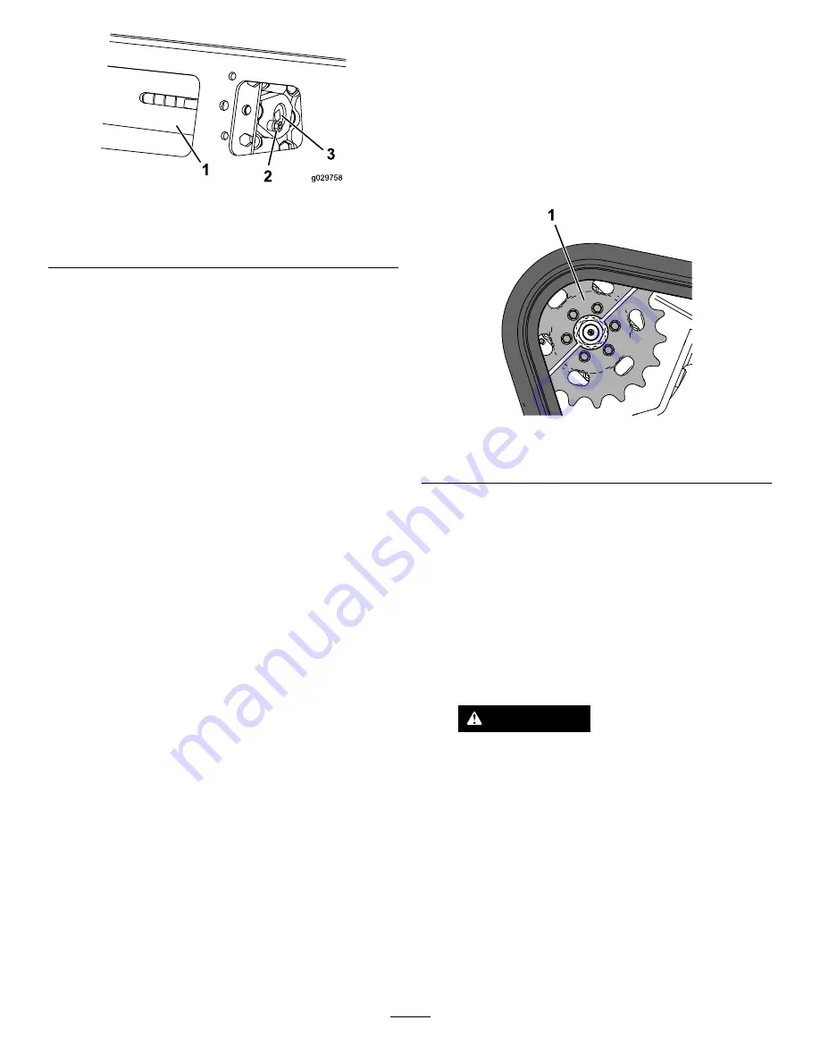
Figure 59

1.

Tension tube

3.

Tensioning screw

2.

Locking bolt

4.

Using a 1/2 inch drive ratchet, turn the tensioning
screw until the tension block aligns with the
green guide on the decal or is 1.3 cm (1/2 inch)
away from the rear of the tension tube slot
(

Figure 58

).

Note:

Turning the screw counter-clockwise

tightens the track; turning the screw clockwise
loosens the track.

5.

Align the closest notch in the tension screw to
the locking-bolt hole and secure the screw with
the locking bolt and nut (

Figure 59

).

6.

Repeat the procedure for the other track.

7.

Drive the machine, then park the machine on a
level surface, engage the parking brake, shut off
the engine, and remove the key.

8.

Verify that the tension block aligns with the
green guide of the decal or is 1.3 cm (1/2 inch)
away from the rear of the tension tube for both
tracks (

Figure 58

). Adjust if necessary.

Replacing the Tracks

Machines with Narrow-Width Tracks

Replace the tracks when they are badly worn.

1.

Remove any attachments.

2.

Park the machine on a level surface, ensuring
that only 1 sprocket half is engaged with the
track (

Figure 60

).

g259714

Figure 60

1.

Sprocket half

3.

Engage the parking brake.

4.

Lower the loader arms so that they are
approximately 20 to 25 cm (8 to 10 inches)
above the frame.

5.

Shut off the engine and remove the key.

6.

Raise the machine off the ground until you
can access the inside of the track beneath
the machine. Support the machine using jack
stands.

Note:

Use jack stands rated for your machine.

WARNING

Mechanical or hydraulic jacks may fail to
support the machine and cause serious
injury.

Use jack stands when supporting the
machine.

7.

Remove the locking bolt, spacer, and nut (

Figure

57

).

8.

Using a 1/2-inch drive ratchet, release the
drive tension by turning the tensioning screw
clockwise (

Figure 57

and

Figure 61

).

40


Содержание TX 1000 Compact Tool Carrier

Страница 1: ...327 Serial No 402000000 and Up Model No 22327G Serial No 402800000 and Up Model No 22327HD Serial No 402000000 and Up Model No 22328 Serial No 403330000 and Up Model No 22328HD Serial No 403100000 and Up Register at www Toro com Original Instructions EN 3423 965 A ...

Страница 2: ...earth and materials moving activities for landscaping and construction work It is designed to operate a wide variety of attachments each of which perform a specialized function Read this information carefully to learn how to operate and maintain your product properly and to avoid injury and product damage You are responsible for operating the product properly and safely You may contact Toro direct...

Страница 3: ...ine 28 Engine Maintenance 29 Engine Safety 29 Servicing the Air Cleaner 29 Servicing the Engine Oil 30 Fuel System Maintenance 32 Draining the Fuel Filter Water Separator 32 Replacing the Fuel Filter Canister and In Line Filter 32 Checking the Fuel Lines and Connections 33 Bleeding the Fuel System 33 Draining the Fuel Tank s 33 Electrical System Maintenance 34 Electrical System Safety 34 Servicing...

Страница 4: ... front of the machine the heavy end Most other attachments make the front of the machine the heavy end Have the property or work area marked for buried lines and other objects and do not dig in marked areas Read and understand the content of this Operator s Manual before starting the engine Use your full attention while operating the machine Do not engage in any activity that causes distractions o...

Страница 5: ...ear eye protection 9 Flush eyes immediately with water and get medical help fast 5 Read the Operator s Manual 10 Contains lead do not discard decal93 6681 93 6681 1 Cutting dismemberment hazard fan stay away from moving parts decal93 7814 93 7814 1 Entanglement hazard belt stay away from moving parts decal93 9084 93 9084 1 Lift point Tie down point decal115 2047 115 2047 1 Warning do not touch the...

Страница 6: ...ting hazard keep away from the attachment and the lift arm decal130 7637 130 7637 1 Blinking light engine coolant temperature 6 Engine start 2 Steady light engine oil pressure 7 Parking brake disengaged 3 Blinking light glow plug 8 Traction neutral 4 Steady light battery warning 9 Auxiliary lever neutral 5 Hourmeter decal131 0709 131 0709 1 Parking brake engage 2 Parking brake disengage decal131 0...

Страница 7: ...attery power disconnect 3 Off 2 On 4 Read the Operator s Manual decal136 5750 136 5750 1 Read the Operator s Manual 2 Tension block guide decal137 9030 137 9030 1 Engine stop 3 Engine start 2 Engine run decal133 8056 133 8056 7 ...

Страница 8: ...decal131 0597 131 0597 decal131 0708 131 0708 1 Move forward 3 Move rearward 2 Turn right 4 Turn left 8 ...

Страница 9: ...chine 10 Tipping hazard always move up or down slopes with the attachment lowered never drive on a slope with the attachment raised always operate with the heavy end uphill always carry loads low never jerk the control levers use a steady even motion 5 Electrocution hazard power lines check for power lines in the area before using the machine 11 Tipping hazard do not make fast turns always check b...

Страница 10: ...Key switch 3 Reference bar 8 Traction control 4 Plug 9 Loader arm attachment tilt lever 5 Auxiliary hydraulics lever 10 Loader lock Key Switch The key switch used to start and shut off the engine has 3 positions OFF RUN and START Refer to Starting the Engine page 18 Throttle Lever Move the control forward to increase the engine speed and rearward to decrease speed Reference Bar When driving the tr...

Страница 11: ...ing look behind you for obstructions and keep your hands on the reference bar g259647 Figure 7 To turn right rotate the traction control clockwise Figure 8 g259649 Figure 8 To turn left rotate the traction control counterclockwise Figure 9 g259648 Figure 9 To stop the machine release the traction control Figure 5 Note The farther you move the traction control in any direction the faster the machin...

Страница 12: ...e loader arms By moving the lever to an intermediate position e g forward and left you can move the loader arms and tilt the attachment at the same time Loader Valve Lock The loader valve lock secures the loader arm attachment tilt lever so that you cannot push it forward This helps to ensure that no one accidentally lowers the loader arms during maintenance Secure the loader arms with the lock an...

Страница 13: ...liary Hydraulics Lock Switch Use your right foot to press the auxiliary hydraulics lock switch to continue the forward or reverse flow of the auxiliary hydraulics and free your hand for other controls Figure 13 g205234 Figure 13 1 Auxiliary hydraulics lock switch Parking Brake Lever To engage the parking brake rotate the lever to left Figure 14 Note The traction unit may roll slightly before the b...

Страница 14: ...ks g029665 Figure 16 Glow Plug Light The light on the right flashes while the glow plugs are charged and warming the engine Figure 17 g029668 Figure 17 Battery Charge Light If the battery charge becomes too low the light on the right illuminates steadily Figure 18 If this happens shut off the engine and charge or replace the battery Refer to Servicing the Battery page 34 g029667 Figure 18 Hour Met...

Страница 15: ... warranty Operation Note Determine the left and right sides of the machine from the normal operating position Before Operation Before Operation Safety General Safety Never allow children or untrained people to operate or service the machine Local regulations may restrict the age or require certified training of the operator The owner is responsible for training all operators and mechanics Become f...

Страница 16: ...rve this caution will damage the engine Biodiesel Ready This machine can also use a biodiesel blended fuel of up to B20 20 biodiesel 80 petrodiesel The petrodiesel portion should be low or ultra low sulfur Observe the following precautions The biodiesel portion of the fuel must meet specification ASTM D6751 or EN14214 The blended fuel composition should meet ASTM D975 or EN590 Painted surfaces may...

Страница 17: ...n and use caution when making turns and crossing roads and sidewalks Watch for traffic Stop the attachment when you are not working Stop the machine turn off the engine remove the key and inspect the machine if you strike an object Make any necessary repairs before resuming operation Never run an engine in an enclosed area Never leave a running machine unattended Before leaving the operating posit...

Страница 18: ...ottle lever midway between the SLOW and FAST positions 4 Insert the key into the key switch and turn it to the ON position 5 Wait for the glow plug indicator light to stop blinking 6 Turn the key to the START position When the engines starts release the key Important Do not engage the starter for more than 10 seconds at a time If the engine fails to start wait 30 seconds for the starter to cool do...

Страница 19: ...f the machine The warranty of the machine may be voided if you use the machine with unapproved attachments Important Before installing the attachment ensure that the mount plates are free of any dirt or debris and that the pins rotate freely If the pins do not rotate freely grease them 1 Position the attachment on a level surface with enough space behind it to accommodate the machine 2 Start the e...

Страница 20: ...oard or paper to find hydraulic leaks never use your hands CAUTION Hydraulic couplers hydraulic lines valves and hydraulic fluid may be hot If you contact hot components you may be burned Wear gloves when operating the hydraulic couplers Allow the machine to cool before touching hydraulic components Do not touch hydraulic fluid spills If the attachment requires hydraulics for operation connect the...

Страница 21: ... be hot from operation Allow them to cool before attempting to maintain adjust or service the machine Use care when loading or unloading the machine into a trailer or truck Moving a Non Functioning Machine Important Do not tow or pull the machine without first opening the tow valves or you will damage the hydraulic system 1 Shut off the engine and remove the key 2 Open the hood and secure the hood...

Страница 22: ...on while driving the machine on a ramp as this could cause a loss of control or a tip over situation 1 If using a trailer connect it to the towing vehicle and connect the safety chains 2 If applicable connect the trailer brakes 3 Lower the ramp Figure 27 4 Lower the loader arms 5 Load the machine onto the trailer with the heavy end up the ramp carrying loads low Figure 28 If the machine has a full...

Страница 23: ...non load carrying attachment e g stump grinder back it down the ramp If the machine has an empty load carrying attachment or no attachment drive it forward down the ramp g204458 Figure 30 1 Machine with full attachment or non load carrying attachment back the machine down the ramp 2 Machine with empty or no attachment drive the machine forward down the ramp Lifting the Machine You can lift the mac...

Страница 24: ...t level in the expansion tank Check and clean the radiator screen Test the parking brake Remove debris from the machine Check for loose fasteners Every 25 hours Remove the air cleaner cover clean out debris and check the air filter service indicator Check the hydraulic fluid level Every 50 hours Check the battery condition Check and adjust the track tension Every 100 hours Change the engine oil Se...

Страница 25: ...engine running Keep all parts in good working condition and all hardware tightened Replace all worn or damaged decals Do not tamper with the safety devices Use only Toro approved attachments Attachments can change the stability and the operating characteristics of the machine You may void the warranty if you use the machine with unapproved attachments Use only genuine Toro replacement parts If any...

Страница 26: ...oods and screens shut off the engine remove the key from the key switch and allow the engine to cool Opening the Hood 1 Loosen the hood locking screw Figure 32 g031215 Figure 32 1 Hood locking screw 3 Hood 2 Hood latch lever 2 Turn the hood latch clockwise Figure 32 3 Lift up on the handles and swing the hood up Figure 32 4 Secure the prop rod Closing the Hood 1 Lift up on the tab securing the pro...

Страница 27: ...reen Removing the Front Screen 1 Open the hood and secure the hood prop 2 Loosen the 2 top bolts and 2 front bolts g247902 Figure 36 1 Bolt 3 Remove the screen Removing the Front Cover 1 Remove the 2 upper bolts 3 8 x 1 inch 2 washers and 2 lower bolts 5 16 x 5 8 inch from the front cover 2 Remove the front cover g204032 Figure 37 1 Upper bolt 3 8 x 1 inch 2 3 Washer 2 2 Front cover 4 Lower bolt 5...

Страница 28: ...loader arms 2 Shut off the engine and remove the key 3 Clean the grease fittings with a rag 4 Connect a grease gun to each fitting Figure 38 Figure 39 and Figure 40 Note Raise the loader arms before greasing the fittings in Figure 40 g031219 g031219 Figure 38 g004209 Figure 39 g029953 Figure 40 5 Pump grease into the fittings until grease begins to ooze out of the bearings approximately 3 pumps 6 ...

Страница 29: ... pull the air cleaner cover off the air cleaner body Figure 41 Important Do not remove the air filter g031236 Figure 41 1 Dust cap 4 Primary filter 2 Latch 5 Air filter body 3 Air cleaner cover 6 Service indicator 6 Squeeze the dust cap sides to open it and knock the dust out 7 Clean the inside of the air cleaner cover with compressed air that is under 205 kPa 30 psi Important Do not use compresse...

Страница 30: ...allons Viscosity See the table below g238048 Figure 42 Checking the Engine Oil Level 1 Park the machine on a level surface engage the parking brake and lower the loader arms 2 Shut off the engine remove the key and allow the engine to cool 3 Open the hood and secure the prop rod 4 Clean the area around the oil dipstick and oil fill cap Figure 43 g029940 Figure 43 1 Oil fill cap 2 Oil dipstick 5 Ch...

Страница 31: ... cap Changing the Oil Filter 1 Raise the loader arms and secure with the cylinder locks refer to Installing the Cylinder Locks page 25 2 Engage the parking brake shut off the engine and remove the key 3 Remove the front cover refer to Removing the Front Cover page 27 4 Drain the oil from the engine refer to Changing the Engine Oil page 30 5 Place a shallow pan or rag under the filter to catch oil ...

Страница 32: ... Every 400 hours 1 Park the machine on a level surface engage the parking brake and lower the loader arms 2 Shut off the engine and remove the key 3 Open the rear access cover refer to Opening the Rear Access Cover page 26 4 Locate the fuel filters on the right side of the engine Figure 47 and place a clean container under it 5 Clean the area where the filter canister mounts Figure 47 6 Remove the...

Страница 33: ...the Fuel System You must bleed the fuel system before starting the engine if any of the following situations have occurred Initial startup of a new machine The engine has ceased running due to a lack of fuel Maintenance has been performed upon fuel system components e g filter replaced 1 Turn the key to the RUN position 2 Let the fuel pump run for 2 minutes prior to starting the machine Draining t...

Страница 34: ... Battery Service Interval Every 50 hours Using the Battery Disconnect Switch WARNING Contact with hot surfaces may cause personal injury Keep your hands feet face clothing and other body parts away the muffler and other hot surfaces 1 Park the machine on a level surface engage the parking brake and lower the loader arms 2 Shut off the engine and remove the key 3 Open the hood secure the prop rod a...

Страница 35: ...ys keep the battery fully charged 1 265 specific gravity This is especially important to prevent battery damage when the temperature is below 0 C 32 F 1 Remove the battery from the machine refer to Removing the Battery page 35 2 Charge the battery for 4 to 8 hours at a rate of 3 to 4 A Figure 50 Do not overcharge the battery g003792 Figure 50 1 Positive battery post 3 Red charger lead 2 Negative b...

Страница 36: ...e with a solution of baking soda and water 5 Rinse the battery with clear water 6 Coat the battery posts and cable connectors with Grafo 112X skin over grease Toro Part No 505 47 or petroleum jelly to prevent corrosion 7 Install the battery refer to Installing the Battery page 36 Installing the Battery Install the battery as shown in Figure 51 g204572 Figure 51 Servicing a Replacement Battery The ...

Страница 37: ...ost Figure 52 g033902 Figure 52 1 Jump post 3 Connect an end of the positive jumper cable to the jump post Figure 52 4 Connect the other end of the positive jumper cable to the positive terminal of the battery in the other machine 5 Connect an end of the negative jumper cable to the negative post of the battery in the other machine 6 Connect the other end of the negative jumper cable to a ground p...

Страница 38: ...daily Clean the tracks Before each use or daily Check the tracks for excessive wear and proper tension Cleaning the Tracks 1 Park the machine on a level surface and engage the parking brake 2 With the bucket installed and pointing down lower it into the ground so that the front of the traction unit lifts off the ground a few centimeters inches 3 Shut off the engine and remove the key 4 Using a wat...

Страница 39: ... 12 7 mm 1 2 inch as shown in Figure 56 Note Turning the screw counter clockwise tightens the track turning the screw clockwise loosens the track 6 Align the closest notch in the tension screw to the locking bolt hole and secure the screw with the locking bolt and nut Figure 57 7 Repeat the procedure for the other track 8 Drive the machine then park the machine on a level surface engage the parkin...

Страница 40: ...he tension tube for both tracks Figure 58 Adjust if necessary Replacing the Tracks Machines with Narrow Width Tracks Replace the tracks when they are badly worn 1 Remove any attachments 2 Park the machine on a level surface ensuring that only 1 sprocket half is engaged with the track Figure 60 g259714 Figure 60 1 Sprocket half 3 Engage the parking brake 4 Lower the loader arms so that they are app...

Страница 41: ...els and wrap it around the frame Figure 61 16 Start the engine and disengage the parking brake 17 Move the traction control forward until the drive sprocket half engages with the track Figure 64 g259737 Figure 64 18 Engage the parking brake shut off the engine and remove the key 19 Apply thread locking compound to the bolts of the drive sprocket half that you removed and install the sprocket half ...

Страница 42: ...ner 3 Front wheel 7 Ratchet 1 2 inch 4 Rear bolt 6 Loosen the rear bolt near the drive wheel Figure 65 7 Remove the nut securing the outer front wheel and remove the wheel Figure 66 g217640 Figure 66 1 Nut 3 Outer front wheel 2 Washer 4 Track 8 Remove the track Figure 66 9 Pull the 2 large washers out of the outer wheels 1 on each side of each wheel Figure 66 10 Clean the old grease and dirt out o...

Страница 43: ... parts can cause severe burns Always allow the engine to cool at least 15 minutes before removing the radiator cap Use a rag when opening the radiator cap and open the cap slowly to allow steam to escape Servicing the Cooling System Service Interval Before each use or daily Clean the screen oil cooler and front of the radiator more often in dirty or dusty conditions Before each use or daily Check ...

Страница 44: ...lant Service Interval Yearly Have an Authorized Service Dealer change the engine coolant yearly If you need to add engine coolant refer to Checking the Engine Coolant Level page 43 Brake Maintenance Testing the Parking Brake Service Interval Before each use or daily 1 Engage the parking brake refer to Parking Brake Lever page 13 2 Start the engine 3 Slowly attempt to drive the machine forward or r...

Страница 45: ...ore performing any work on the hydraulic system Hydraulic Fluid Specifications Hydraulic Tank Capacity 37 9 L 10 US gallons Use only 1 of the following fluids in the hydraulic system Toro Premium Transmission Hydraulic Tractor Fluid refer to your Authorized Service Dealer for more information Toro Premium All Season Hydraulic Fluid refer to your Authorized Service Dealer for more information If ei...

Страница 46: ...rod 6 Remove the right side screen 7 Clean the area around the filler neck of the hydraulic tank Figure 69 g029748 Figure 69 1 Filler neck cap 8 Remove the filler neck cap and check the fluid level on the dipstick Figure 70 Note The fluid level should be between the 2 notches of the dipstick while the arms are lowered or at the lower notch while the arms are raised g029729 Figure 70 1 Filler neck ...

Страница 47: ...emove the right side screen refer to Removing the Side Screens page 27 6 Remove the hydraulic tank cap and dipstick Figure 72 g029729 Figure 72 1 Filler neck 2 Dipstick 7 Place a large drain pain capable of holding 57 L 15 US gallons under the drain plug on the front of the machine Figure 73 g031213 Figure 73 1 Drain plug 8 Remove the drain plug and allow the oil to drain into the pan Figure 73 9 ...

Страница 48: ...sis Service Interval Every 100 hours Check for dirt buildup in the chassis Over time the chassis under the engine collects dirt and debris that must be removed Using a flashlight open the hood and inspect the area under the engine regularly When the debris is 2 5 to 5 cm 1 to 2 inches deep clean the chassis 1 Park the machine on a level surface engage the parking brake and lower the loader arms 2 ...

Страница 49: ...e hydraulic pumps and motors 4 Service the air cleaner refer to Servicing the Air Cleaner page 29 5 Grease the machine refer to Greasing the Machine page 28 6 Change the engine oil refer to Changing the Engine Oil page 30 7 Charge the battery refer to Charging the Battery page 35 8 Check and adjust the track tension refer to Adjusting the Track Tension page 39 9 Check and tighten all fasteners Rep...

Страница 50: ...fuel line is clogged 5 Clean or replace the fuel line 6 There is air in the fuel 6 Bleed the nozzles and check for air leaks at the fuel hose connections and fittings between the fuel tank and engine 7 The glow plugs are inoperative 7 Check the fuse glow plugs and wiring 8 The cranking speed is slow 8 Check the battery oil viscosity and starting motor contact your Authorized Service Dealer 9 The a...

Страница 51: ...air in the fuel 3 Bleed the nozzles and check for air leaks at the fuel hose connections and fittings between the fuel tank and engine 4 The injection nozzles are damaged 4 Contact your Authorized Service Dealer 5 There is low compression 5 Contact your Authorized Service Dealer 6 The injection pump timing is incorrect 6 Contact your Authorized Service Dealer 7 There is excessive carbon buildup 7 ...

Страница 52: ... fuel system 4 Drain and flush the fuel system add fresh fuel 5 The engine is overheating 5 Refer to The engine overheats 6 The spark arrestor screen is clogged 6 Clean or replace the spark arrestor screen 7 There is air in the fuel 7 Bleed the nozzles and check for air leaks at fuel hose connections and fittings between the fuel tank and engine 8 There is low compression 8 Contact your Authorized...

Страница 53: ...compression 6 Contact your Authorized Service Dealer 1 The parking brake is engaged 1 Disengage the parking brake 2 The hydraulic fluid level is low 2 Add hydraulic fluid to the reservoir 3 The hydraulic system is damaged 3 Contact your Authorized Service Dealer 4 The tow valves are open 4 Close the tow valves 5 The flow divider valve lever is in 9 o clock position 5 Move the lever to the 12 o clo...

Страница 54: ...Schematics g240932 Electrical Schematic Rev B 54 ...

Страница 55: ...g260360 Hydraulic Schematic Rev D 55 ...

Страница 56: ...Notes ...

Страница 57: ...Notes ...

Страница 58: ...Notes ...

Страница 59: ...f these activities We will not sell your personal information to any other company We reserve the right to disclose personal information in order to comply with applicable laws and with requests by the appropriate authorities to operate our systems properly or for our own protection or that of other users Retention of your Personal Information We will keep your personal information as long as we n...

Страница 60: ...to restaurants grocery stores hotels schools and hospitals and on a wide variety of products Additionally some online and mail order retailers provide Prop 65 warnings on their websites or in catalogs How do the California warnings compare to federal limits Prop 65 standards are often more stringent than federal and international standards There are various substances that require a Prop 65 warnin...

Отзывы: